Step
1 << 2 << 3 << 4 << 5 << 6 << 7 << 8 << 9 << 10 << 11 << 12 << 13 << 14 << 15 << MSC.Patran home
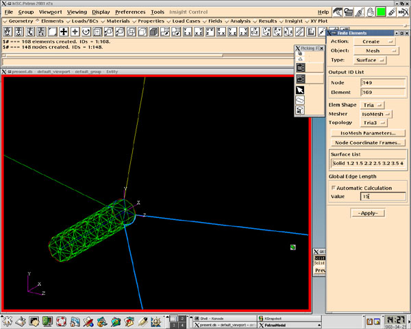
The next step is to actually create the triangular surface mesh.
To do this select "Create" under the "Action" pull down menu, "Mesh" under the "Object" pull down menu, "Surface" under the "Type" pull down menu, and "Tria" under the "Elem Shape" pull down menu. Now you have to find out what you want to mesh. The cylinder has surfaces all along the exterior and along the interior and we do not want to mesh everything. In our diagram there are 4 extruded solids making up the cylinder. Anytime you extrude in MSC.Patran it always creates 6 parts to the solid. 5 and 6 are the beginning and ending points respectively and 1 through 4 are the sections in between. (Hint: if you type in Solid 1.1 under "Surface List" and click outside of the box MSC.Patran will change the color of Solid 1.1 to orange so you know, which one is which) In our case Solid #.1 is a line, Solid #.2 is the outer curved surface, #.3 is one of the internal corner pieces, #.4 is the other internal corner piece, #.5 is the starting point of the solid, and #.6 is the opposite end of the solid (which in the simulation needs to be open). If you type "Solid 1.2 2.2 3.2 4.2 1.5 2.5 3.5 4.5" under "Surface List" MSC.Patran will calculate the "Global Edge Length" for the selection. Node points are shared and it is easier if you do mesh generation in chunks. The higher the "Global Edge Length" the wider the mesh and the lower it is the tighter the mesh will be. Incidentally I chose 15. Just hit apply and MSC.Patran will create the mesh for you.
