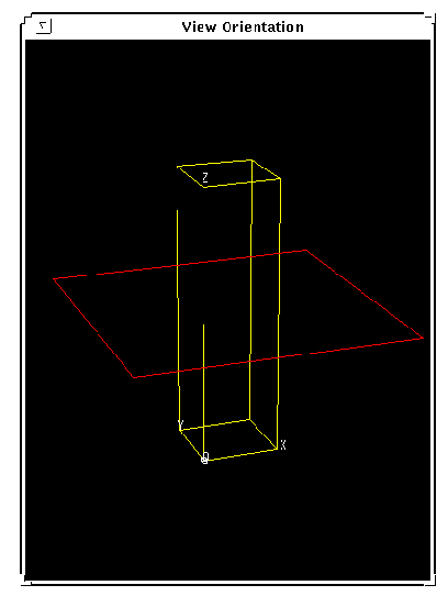
 The number of the graphics window to use for the View Orientation window. Since this window is left on the screen when VIEWER returns, it is up to the calling program to delete it when desired. (The View Control window is automatically deleted when VIEWER returns.)
xsize, ysize
 The X and Y dimensions, respectively, of the graphics window that VIEWER is setting up the view for.
size_fac
 A factor controlling the size of the View Orientation window. The X dimension of the View Orientation window is (size_fac * xsize) and the Y dimension is (size_fac * ysize). Typically, size_fac should be in the range 0.5 to 1.0.
xpos, ypos
 The location (x and y positions, respectively) for the View Orientation and View Control windows.
If the View Orientation window is near the bottom of the screen, then the View Control window is created above the View Orientation window. Otherwise, the View Control window is created below the View Orientation window.
colors
 The value (number of colors to allocate) to use as the Colors keyword value in the WINDOW procedure call. A typical value for an 8-bit color system is 128 or 256.
retain
 The value (flag) to use as the Retain keyword value in the WINDOW procedure call. Typically this is the value 1 or 2.
 For more information on colors and retain, see the description of the WINDOW procedure in the PV-WAVE Reference.
xdim, ydim, zdim
 The size (first, second, and third dimension, respectively) of the array containing the data that is displayed using the view specified by VIEWER.
For example, if a 20-by-30-by-40 array is to be displayed using SHADE_VOLUME and POLYSHADE, then xdim should be 20, ydim should be 30, and zdim should be 40.
If a 20-by-30 array is to be displayed using the SURFACE or CONTOUR procedures, then xdim should be 20, ydim should be 30, and zdim should be
(MAX(array)+1.0).
 .size 32766 32766


 Alt
Alt

