Copyright © 1997 by Rikk Carey and Gavin Bell
This chapter describes key concepts related to the definition and use of the VRML specification. This includes syntax fundamentals, how nodes are combined into scene graphs, how nodes receive and generate events, how to create new node types using prototypes, how to distribute and share new nodes, how to incorporate user-programmed scripts into a VRML file, and various general topics on nodes.
This chapter quickly jumps into technical details. If you are looking for an overview or introduction, read Chapter 1, Introduction, or one of the recommended tutorial books listed in Appendix F.
This chapter describes key concepts of the definition and use of the VRML standard. This includes how nodes are combined into scene graphs, how nodes receive and generate events, how to create node types using prototypes, how to add node types to VRML and export them for use by others, how to incorporate scripts into a VRML file, and various general topics on nodes.
See Table 2-1 for the table of contents for this chapter.
The following conventions are used throughout this standard:
Italics are used for event and field names, and are also used when new terms are introduced and equation variables are referenced.
A fixed-space font is used for URL addresses and source
code examples. VRML file examples appear in bold,
fixed-space font.
Node type names are appropriately capitalized (e.g., "The Billboard node is a grouping node..."). However, the concept of the node is often referred to in lower case in order to refer to the semantics of the node, not the node itself (e.g., "To rotate the billboard...", "A special case of billboarding is...").
Throughout this document references are denoted using the "[ABCD]" notation, where "[ABCD]" is an abbreviation of the reference title that is described in detail in the Bibliography.
A VRML file consists of the following major functional components: the header, the scene graph, the prototypes, and event routing. The contents of this file are processed for presentation and interaction by a mechanism known as a browser.
For easy identification of VRML files, every VRML file shall begin with:
#VRML V2.0 <encoding type> [comment] <line terminator>
The header is a single line of UTF-8 text identifying the file as a VRML file and identifying the encoding type of the file. It may also contain additional semantic information. There shall be exactly one space separating "#VRML" from "V2.0", "V2.0" from "<encoding type>", and "<encoding type>" from "[optional comment]".
The <encoding type> is either "utf8" or any other authorized values defined in other parts of ISO/IEC 14772. The identifier "utf8" indicates a clear text encoding that allows for international characters to be displayed in VRML using the UTF-8 encoding defined in ISO 10646-1 (otherwise known as Unicode); see [UTF8]. The usage of UTF-8 is detailed under the specification of the Text node. The header for a UTF-8 encoded VRML file is
#VRML V2.0 utf8 [optional comment] <line terminator>
Any characters after the <encoding type> on the first
line may be ignored by a browser. The header line ends at the
occurrence of a <line terminator>. A <line
terminator> is a linefeed character (0x0A) or a carriage
return character (0x0D) .
Extra characters on the first line after the mandatory #VRML V2.0 utf8 are allowed so that tools have a convenient place to store tool-specific information about the VRML file. For example, a program that generates VRML files might append information about which version of the program generated the file:
#VRML V2.0 utf8 Generated by VRML-o-matic V1.3
However, like other comments in the VRML file, the extra information on the first line may not be preserved by tools that read and write VRML files. A more reliable technique is to save the tool-specific information in a WorldInfo node (see section Chapter 3, Node Reference, WorldInfo).
The scene graph contains nodes which describe objects and their properties. It contains hierarchically grouped geometry to provide an audio-visual representation of objects, as well as nodes that participate in the event generation and routing mechanism.
Prototypes allow the set of VRML node types to be extended by the user. Prototype definitions can be included in the file in which they are used or defined externally. Prototypes may be defined in terms of other VRML nodes or may be defined using a browser-specific extension mechanism. While VRML has a standard format for identifying such extensions, their implementation is browser-dependent.
Some VRML nodes generate events in response to environmental changes or user interaction. Event routing gives authors a mechanism, separate from the scene graph hierarchy, through which these events can be propagated to effect changes in other nodes. Once generated, events are sent to their routed destinations in time order and processed by the receiving node. This processing can change the state of the node, generate additional events, or change the structure of the scene graph.
Script nodes allow arbitrary, author-defined event processing. An event received by a Script node causes the execution of a script function which has the ability to send events through the normal event-routing mechanism, or bypass this mechanism and send events directly to any node to which the Script node has a reference. Scripts can also dynamically add or delete routes and thereby change the event-routing topology.
The ideal event model processes all events instantaneously in the order that they are generated. A timestamp, the time at which an event is delivered to a node, serves two purposes. First, it is a conceptual device used to describe the chronological flow of the event mechanism. It ensures that deterministic results can be achieved by real-world implementations which must address processing delays and asynchronous interaction with external devices. Second, timestamps are also made available to Script nodes to allow events to be processed based on the order of user actions or the elapsed time between events.
A generator is a human or computerized creator of VRML files. It is the responsibility of the generator to ensure the correctness of the VRML file and the availability of supporting assets (e.g., images, audio clips, other VRML files) referred to therein.
The interpretation, execution, and presentation of VRML files will typically be undertaken by a mechanism known as a browser, which displays the shapes and sounds in the scene graph. This presentation is known as a virtual world and is navigated in the browser by a human or mechanical entity, known as a user. The world is displayed as if experienced from a particular location; that position and orientation in the world is known as the viewer. The browser may define navigation paradigms (such as walking or flying) that enables the user to move the viewer through the virtual world.
In addition to navigation, the browser may provide a mechanism allowing the user to interact with the world through sensor nodes in the scene graph hierarchy. Sensors respond to user interaction with geometric objects in the world, the movement of the user through the world, or the passage of time.
The visual presentation of geometric objects in a VRML world follows a conceptual model designed to resemble the physical characteristics of light. The VRML lighting model describes how appearance properties and lights in the world are combined to produce displayed colours.
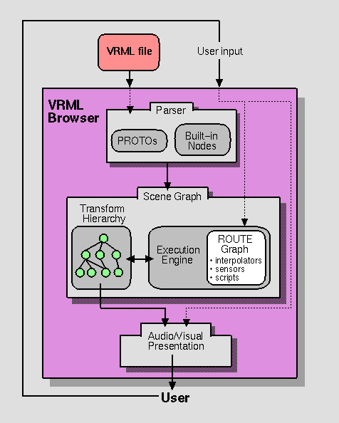
Figure 2-1 illustrates a conceptual model of a VRML browser. This diagram is for illustration purposes only and is not intended for literal implementation. The browser is portrayed as a presentation application that accepts user input in the forms of file selection (explicit and implicit) and user interface gestures (e.g., manipulation and navigation using an input device). The three main components of the browser are: Parser, Scene Graph, and Audio/Visual Presentation. The Parser component reads the VRML file and creates a Scene Graph. The Scene Graph component consists of a Transform Hierarchy (the nodes) and a ROUTE Graph (the connections between nodes). The Scene Graph also includes an Execution Engine that processes events, reads and edits the ROUTE Graph, and makes changes to the Transform Hierarchy (nodes). User input generally affects sensors and navigation, and thus is wired to the ROUTE Graph component (sensors) and the Audio/Visual Presentation component (navigation). The Audio/Visual Presentation component performs the graphics and audio rendering of the Transform Hierarchy that feeds back to the user.
VRML conceptually supports the concepts of profiles. A profile is a named collection of functionality which must be supported in order for an implementation to be conformant to that profile. Only one profile is defined in this standard. The functionality and minimum support requirements described in ISO/IEC 14772-1 form the Base profile for VRML. Additional profiles may be defined in other parts of ISO/IEC 14772. Such profiles shall incorporate the entirety of the Base profile.
This section describes the syntax of UTF-8-encoded, human-readable VRML files. A more formal description of the syntax may be found in Appendix A, "Grammar Reference." The semantics of VRML are presented in this part of ISO/IEC 14772 in terms of the UTF-8 encoding. Other encodings may be defined in other parts of ISO/IEC 14772. Such encodings shall describe how to map the UTF-8 descriptions to and from the corresponding encoding elements.
For the UTF-8 encoding, the # character begins a comment. Only the first comment (the file header) has semantic meaning. Otherwise, all characters following a # until the next line terminator are ignored. The only exception is within double-quoted SFString and MFString fields where the # character is defined to be part of the string.
Commas, spaces, tabs, linefeeds, and carriage-returns are separator characters wherever they appear outside of string fields. One or more separator characters separate the syntactical entities in VRML files, where necessary. The separator characters collectively are termed whitespace.
Commas are treated as whitespace characters to ease the transition from the VRML 1.0 file format syntax. Equating commas to whitespace does not hamper parsing and allows both the VRML 1.0 syntax for multiple-valued fields (which required commas) and the VRML 1.0 syntax for MFNode child lists (which were a special case in VRML 1.0 and required that the children be separated by blank/tab/newline).
Comments and separators need not be preserved. In particular, a VRML document server may strip comments and extra separators from a VRML file before transmitting it. WorldInfo nodes should be used for persistent information such as copyrights or author information.
Note: In the following paragraph, the form "0xhh" expresses a byte as a hexadecimal number representing the bit configuration for that byte.
Field, event, PROTO, EXTERNPROTO, and node names shall not contain control characters (0x0-0x1f, 0x7f), space (0x20), double or single quotes (0x22: ", 0x27: '), sharp (0x23: #), comma (0x2c: ,), period (0x2e: .), square brackets (0x5b, 0x5d: []), backslash (0x5c: \) or curly braces (0x7b, 0x7d: {}). Further, their first character must not be a digit (0x30-0x39), plus (0x2b: +), or minus (0x2d: -) character. Otherwise, names may contain any ISO 10646 character encoded using UTF-8. VRML is case-sensitive; "Sphere" is different from "sphere" and "BEGIN" is different from "begin."
| First character | All other characters |
| + - 0-9 " ' # , . [ ] \ {} 0x0-0x20 (nonprintable) | " ' # , . [ ] \ {} 0x0-0x20 (nonprintable) |
The following reserved keywords shall not be used for field, event, PROTO, EXTERNPROTO, or node names:
All of these rules make it easier to write a parser that reads VRML files using traditional parsing technology such as YACC and Lex. The public domain VRML 2.0 file format parser donated by Silicon Graphics is an example of such a parser (see http://vrml.sgi.com).
The VRML 2.0 file syntax grew out of the VRML 1.0 file syntax, which came directly from the Open Inventor ASCII file format. The original goals for the Open Inventor file format were simplicity, ease of use, ease of parsing, and small file size.
The VRML 2.0 syntax was changed from the VRML 1.0 syntax in a number of ways based on feedback from VRML 1.0 implementors. Most of the changes make the format more regular and easier to parse, sometimes at the expense of making it more difficult to edit VRML files with a text editor. Deciding where to draw the line between ease of parsing and ease of text editing was one of the many controversial issues debated during the VRML 2.0 design process.
At the time of this writing, a binary, compressed file format for VRML is being defined (http://www.vrml.org/vag/BinaryRFP.html).
After the required header, a VRML file may contain any combination of the following:
A node statement consists of an optional name for the node followed by the node's type and then the body of the node. A node is given a name using the keyword DEF followed by the name of the node. The node's body is enclosed in matching curly braces ("{ }"). Whitespace shall separate the DEF, name of the node, and node type, but is not required before or after the curly braces that enclose the node's body. See "A.3 Nodes" for details on node grammar rules.
[DEF <name>] <nodeType> { <body> }
A node's body consists of any number of field statements, IS statements, ROUTE statements, PROTO statements or EXTERNPROTO statements, in any order.
See "2.3.4 Field statement syntax" for a description of field statement syntax and "2.7 Field, eventIn, and eventOut semantics" for a description of field statement semantics. See "2.6 Node semantics" for a description of node statement semantics.
A field statement consists of the name of the field followed by the field's value(s). The following ilustrates the syntax for a single-valued field:
<fieldName> <fieldValue>
The following illustrates the syntax for a multiple-valued field:
<fieldName> [ <fieldValues> ]
See "A.4 Fields" for details on field statement grammar rules.
Each node type defines the names and types of the fields that each node of that type contains. The same field name may be used by multiple node types. See "Chapter 4, Field and Event Reference" for the definition and syntax of specific field types.
See "2.7 Field, eventIn, and eventOut semantics" for a description of field statement semantics.
A PROTO statement consists of the PROTO keyword, followed in order by the prototype name, prototype interface declaration, and prototype definition:
PROTO <name> [ <declaration> ] { <definition> }
See "A.2 General" for details on prototype statement grammar rules.
The convention used for all nodes defined in the VRML standard (which should be thought of as PROTO's with built-in implementation) is that each word in a node type name begins with a capital letter (e.g., Box, Orientation-Interpolator). Although not enforced, you are encouraged to follow this convention when defining your own node types using PROTO.
A prototype interface declaration consists of eventIn, eventOut, field, and exposedField declarations (see "2.7 Field, eventIn, and eventOut semantics") enclosed in square brackets. Whitespace is not required before or after the brackets.
EventIn declarations consist of the keyword "eventIn" followed by an event type and a name:
eventIn <eventType> <name>
EventOut declarations consist of the keyword "eventOut" followed by an event type and a name:
eventOut <eventType> <name>
Field and exposedField declarations consist of either the keyword "field" or "exposedField" followed by a field type, a name, and an initial field value of the given field type.
    field <fieldType> <name> <initial field value>

    exposedField <fieldType> <name> <initial field value>
Field, eventIn, eventOut, and exposedField names must be unique in each PROTO statement, but are not required to be unique between different PROTO statements. If a PROTO statement contains an exposedField with a given name (e.g., zzz), it must not contain eventIns or eventOuts with the prefix set_ or the suffix _changed and the given name (e.g., set_zzz or zzz_changed).
Allowing nonunique field and event names in different node types makes it much easier to reuse PROTOs defined by different people in the same scene and doesn't make parsing VRML significantly more difficult (because parsers must keep track of the fields and events that are declared for each PROTO type anyway). Forcing all field and event types to be unique between all node types would be very annoying, even just for the nodes defined in the VRML 2.0 standard. For example, all interpolator nodes have set_fraction, key, keyValue, and value_changed fields/events. Defining slightly different names for fields that perform the same function would be confusing and error prone.
A prototype definition consists of at least one node statement and any number of ROUTE statements, PROTO statements, and EXTERNPROTO statements in any order.
See "2.8 Prototype semantics" for a description of prototype semantics.
The body of a node statement that is inside a prototype definition may contain IS statements. An IS statement consists of the name of a field, exposedField, eventIn or eventOut from the node's public interface followed by the keyword IS followed by the name of a field, exposedField, eventIn or eventOut from the prototype's interface declaration:
<field/eventName> IS <field/eventName>
See "A.3 Nodes" for details on prototype node body grammar rules. See "2.8 Prototype semantics" for a description of IS statement semantics.
An EXTERNPROTO statement consists of the EXTERNPROTO keyword followed in order by the prototype's name, its interface declaration, and either one double-quoted string or zero or more double-quoted strings enclosed in square brackets:
EXTERNPROTO <name> [ <declaration> ] URL or [ URLs ]
See "A.2 General" for details on external prototype statement grammar rules.
An EXTERNPROTO interface declaration is the same as a PROTO interface declaration, with the exception that field and exposedField intitial values are not specified and the prototype definition is specified in a separate file referred to by the URL(s).
The syntax for EXTERNPROTO was carefully chosen so that VRML browsers can continue to parse the VRML file without fetching the EXTERNPROTO's definition. This was done for two reasons: First, because the Internet is not a reliable network, and broken or temporarily unavailable links are commonplace, and second, because it is important that VRML browsers be able to delay loading pieces of the world that are not yet needed. Interacting with a partially loaded world while the rest of the world is being sent across the network is an important usability feature.
VRML browsers need to know the field/event names and types for a node type before being able to parse node types that aren't part of the standard. Therefore, you must use a PROTO or EXTERNPROTO declaration before instantiating any new node type.
Several other file formats deal with the problem of new types by defining a syntax that allows them to be skipped during parsing by defining delimiting characters or writing a byte count as the first part of any type. However, the existence of SFNode/MFNode fields along with DEF/USE and ROUTE makes it difficult to use such a scheme with VRML. For example:
        UnknownNode {
          children [ DEF T Transform { ... } ]
        }
        Group {
          children [ USE T ]
        }
If a parser skipped everything inside the new UnknownNode type, then it would generate a syntax error when it later encountered the USE T statement in the Group node since the DEF T statement had been skipped. It would be possible to redesign the node reference mechanisms completely (by requiring all nodes be predefined and referred to via a table of contents structure, for example), but doing so would complicate VRML and make it significantly harder to use. Besides, declaring all of the events and fields for new node types is good style and makes it much easier to implement authoring systems that can deal with new node types.
A USE statement consists of the USE keyword followed by a node name:
USE <name>
See "A.2 General" for details on USE statement grammar rules.
A ROUTE statement consists of the ROUTE keyword followed in order by a node name, a period character, a field name, the TO keyword, a node name, a period character, and a field name. Whitespace is allowed but not required before or after the period characters:
ROUTE <name>.<field/eventName> TO <name>.<field/eventName>
See "A.2 General" for details on ROUTE statement grammar rules.
ROUTE statements are usually put at the end of the VRML file (or the end of a PROTO definition if you are defining routes inside a prototype; see Section 2.6, Prototypes), but it is often convenient to put them in the middle of the file. For example:
        DEF T Transform {
          translation 1 1 1
          ROUTE T.translation_changed TO T.set_center
          center 1 1 1
        }
Allowing ROUTE statements inside nodes makes it easier to create VRML files using a text editor and doesn't make implementing VRML much harder. Implementing parsing of ROUTE statements is essentially equivalent to implementing USE statements, and since USE statements can appear inside nodes that have SFNode/MFNode fields it is not difficult to also implement ROUTE statements inside nodes.
Tools that read and write VRML files are not required to maintain the position of ROUTE statements in the file. They will usually either put all ROUTE statements at the end of the file or will put them in either the source or destination node, depending on which is written last (since a ROUTE statement must appear after both the source and destination nodes have been DEF'ed).
A VRML file contains zero or more root nodes. The root nodes for a file are those nodes defined by the node statements or USE statements that are not contained in other node or PROTO statements. Root nodes must be children nodes (see "2.6.5 Grouping and children nodes").
A VRML file is hierarchical; node statements can contain SFNode or MFNode field statements that, in turn, contain node (or USE) statements. This hierarchy of nodes is called the scene graph. Each arc in the graph from A to B means that node A has an SFNode or MFNode field whose value directly contains node B. See [FOLE] for details on hierarchical scene graphs.
The descendants of a node are all of the nodes in its SFNode or MFNode fields, as well as all of those nodes' descendants. The ancestors of a node are all of the nodes that have the node as a descendant.
The transformation hierarchy includes all of the root nodes and root node descendants that are considered to have one or more particular locations in the virtual world. VRML includes the notion of local coordinate systems, defined in terms of transformations from ancestor coordinate systems (using Transform or Billboard nodes). The coordinate system in which the root nodes are displayed is called the world coordinate system.
A VRML browser's task is to present a VRML file to the user; it does this by presenting the transformation hierarchy to the user. The transformation hierarchy describes the directly perceptible parts of the virtual world.
The following node types are in the scene graph but not affected by the transformation hierarchy: ColorInterpolator, CoordinateInterpolator, NavigationInfo, NormalInterpolator, OrientationInterpolator, PositionInterpolator, Script, ScalarInterpolator, TimeSensor, and WorldInfo. Of these, only Script nodes may have descendants. A descendant of a Script node is not part of the transformation hierarchy unless it is also the descendant of another node that is part of the transformation hierarchy or is a root node.
Nodes that are descendants of LOD or Switch nodes are affected by the transformation hierarchy, even if the settings of a Switch node's whichChoice field or the position of the viewer with respect to a LOD node makes them imperceptible.
The transformation hierarchy shall be a directed acyclic graph; results are undefined if a node in the transformation hierarchy is its own ancestor.
Coordinate systems are a fundamental and difficult topic to understand. There are a variety of books that provide excellent explanations and tutorials on this subject. One that stands out is The OpenGL Programming Guide by Mason Woo, Jackie Neider, and Tom Davis (see Chapter 3, Viewing and Modeling Transformations, in their book).
VRML defines the unit of measure of the world coordinate system to be metres. All other coordinate systems are built from transformations based from the world coordinate system. Table 2-2 lists standard units for VRML.
| Category | Unit |
|---|---|
| Linear distance | Metres |
| Angles | Radians |
| Time | Seconds |
| Colour space | RGB ([0.,1.], [0.,1.], [0. 1.]) |
The VRML convention that one unit equals one meter (in the absence of any scaling Transform nodes) is meant to make the sharing of objects between worlds easier. If everyone models their objects in meters, objects will be the correct size when placed next to each other in the virtual world. Otherwise, a telephone might be as big as a house, which is very inconvenient if you are trying to put the telephone on a desk inside the house.
Put a scaling Transform node on top of your objects if you want to work in some other units of measure (e.g., inches or centimeters). Or, if compatibility with objects other people have created is not important for your use of VRML, then nothing will break if you disregard the one-unit-equals-one-meter convention. For example, if you are modeling galaxies then it probably isn't important that a telephone be the proper real-world scale, and you might just assume that one unit equals one light-year.
Radians were originally chosen for Open Inventor's file format to be compatible with the standard C programming language math library routines. Although another angle representation might be more convenient (e.g., 0.0 to 1.0 or 0.0 to 360.0), the benefits of compatibility have always outweighed the minor inconvenience of doing an occasional multiplication by 2 × pi.
Times are expressed as double-precision floating point numbers in VRML, so nano-second accuracy is possible. Although there are no time transformation functions built into VRML, time values may be manipulated in any of the scripting languages that work with VRML.
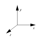
VRML uses a Cartesian, right-handed, three-dimensional coordinate system (see Figure 2-2). By default, the viewer is positioned along the positive Z-axis so as to look along the -Z direction with +Y-axis up. A modelling transformation (see "3.6 Transform" and "3.52 Billboard") or viewing transformation (see "3.53 Viewpoint") can be used to alter this default projection.
The VRML convention of the Y-axis pointing in the up direction is intended to make it easier to share objects. Not only will objects be the right size (assuming they obey the units-equals-meters convention), but they will also be oriented correctly. Walking around worlds is also easier if your VRML browser and the world you load agree about which direction is up; if they disagree, you'll find yourself climbing the walls.
Deciding which way is up was perhaps the longest of all of the debates that happened on the www-vrml mailing list during both the VRML 1.0 and the VRML 2.0 design processes. There are two common conventions: the Y-axis is up (the convention in mathematics and many of the sciences) or the Z-axis is up (the convention for architects and many engineering disciplines). It is easy to convert from one to the other. Putting the following Transform as the root of your VRML files will switch the file from the Z-is-up convention to the VRML-standard Y-is-up:
Transform { rotation 1 0 0 -1.57 children [...] }
The file extension for VRML files is .wrl (for world).
The official MIME type for VRML files is defined as:
model/vrml
where the MIME major type for 3D data descriptions is model, and the minor type for VRML documents is vrml.
For compatibility with earlier versions of VRML, the following MIME type shall also be supported:
x-world/x-vrml
where the MIME major type is x-world, and the minor type for VRML documents is x-vrml.
See [MIME] for details.
MIME types do not encode file format version information, so both the MIME type and the file extension were not changed between VRML 1.0 and VRML 2.0. Changing the MIME type would avoid cryptic error messages like "Not a VRML file" from VRML 1.0 tools that do not understand VRML 2.0. However, this would require that every Web server in the world be configured to support the new file suffix. The most frequently encountered problem with VRML 1.0 files is that Web servers are not configured to serve VRML files. Therefore, changing the MIME type of the suffix would cause more problems than it solved.
Almost all VRML 1.0 files can be transparently converted into VRML 2.0. There are VRML 1.0-to-2.0 file translators available from both Silicon Graphics (http://vrml.sgi.com) and Sony (http://vs.sony.co.jp/VS-E/vstop.html). Also, if you are using VRML 1.0, it is recommended that you avoid MatrixTransform and TransformSeparator since both of these nodes do not translate into VRML 2.0 very well.
A URL (Uniform Resource Locator), described in [URL], specifies a file located on a particular server and accessed through a specified protocol (e.g., http). The upper-case term URL refers to a Uniform Resource Locator, while the italicized lower-case version url refers to a field which may contain URLs, URNs, or in-line encoded data.
All url fields are of type MFString. The strings in these fields indicate multiple locations to look for data in decreasing order of preference. If the browser cannot locate the data specified by the first location, it shall try the second and subsequent locations in order. The url field entries are delimited by double quotation marks " ". Due to the "2.5.4 Data Protocol" and the "2.5.5 Scripting Language Protocols" url fields use a superset of the standard URL syntax (IETF RFC 1738). Details on the string field are located in "4.9 SFString and MFString."
More general information on URLs is described in [URL].
Allowing multiple locations to be specified wherever a VRML file refers to some other file adds some useful features:
           url [ "new://www.vrml.org/foo.wrl"
                 "http://www.other.org/foo.wrl" ]
           url [ "http://server1.com/foo.wrl"
                 "http://server2.com/foo.wrl" ]
Relative URLs are handled as described in [RURL]. The base document for EXTERNPROTO statements or Anchor, AudioClip, ImageTexture, Inline, MovieTexture, and Script node statements is:
The IETF is in the process of standardizing a "Data:" URL to be used for in-line inclusion of base64 encoded data, such as JPEG images. This capability shall be supported as specified in [DATA].
The data: URL scheme is meant to be used for small pieces of data when the overhead of establishing a network connection is much greater than the time it takes to send the data. Some other uses for data: URLs include
The Script node's url field may also support custom protocols for the various scripting languages. For example, a script url prefixed with javascript: shall contain JavaScript source, with line terminators allowed in the string. A script prefixed with javabc: shall contain Java bytecodes using a base64 encoding. The details of each language protocol are defined in the appendix for each language. Browsers are not required to support any specific scripting language. However, browsers shall adhere to the protocol for any scripting language which is supported. The following example illustrates the use of mixing custom protocols and standard protocols in a single url (order of precedence determines priority):
    #VRML V2.0 utf8
    Script {
      url [ "javascript: ...",           # custom protocol
            "http://bar.com/foo.js",     # std protocol
            "http://bar.com/foo.class" ] # std protocol
    }
In the example above, the "..." represents in-line JavaScript source code.
These new VRML-specific "protocols" were added to make it easier to create behaviors with a text editor and they don't follow the strict URL syntax as specified by the IETF (which requires certain common punctuation to be encoded, for example).
URNs are location-independent pointers to a file or to different representations of the same content. In most ways, URNs can be used like URLs except that, when fetched, a smart browser should fetch them from the closest source. URN resolution over the Internet has not yet been standardized. However, URNs may be used now as persistent unique identifiers for referenced entities such as files, EXTERNPROTOs, and textures. General information on URNs is available at [URN].
URNs may be assigned by anyone with a domain name. For example, if the company Foo owns foo.com, it may allocate URNs that begin with "urn:inet:foo.com:". An example of such usage is "urn:inet:foo.com:texture:wood001". See the draft specification referenced in [URN] for a description of the legal URN syntax.
To reference a texture, EXTERNPROTO, or other file by a URN, the URN is included in the url field of another node. For example:
    ImageTexture {
      url [ "http://www.foo.com/textures/wood_floor.gif",
            "urn:inet:foo.com:textures:wood001" ]
    }
specifies a URL file as the first choice and a URN as the second choice.
It is hoped that eventually there will be a standard set of VRML data files that will be widely distributed and frequently used by world creators—a standard library of objects, textures, sounds, and so forth. If a common set of resources are agreed on, they could be distributed and loaded from a CD-ROM or hard disk on a user's local machine, resulting in much faster load times. The world creator would merely refer to things by their standard URN name. The VRML browser will know the location of the "nearest" copy, whether already loaded into memory, on a CD in the local CD-ROM drive, or located somewhere on the network.
Each node may have the following characteristics:
Nodes in general may have a couple of other characteristics:
The most commonly used values have been selected as the default values for each field. Therefore, it is recommended that you do not explicitly specify fields with default values since this will unnecessarily increase file size.
VRML's object model doesn't really match any of the object models found in formal programming languages (object oriented, delegation, functional, etc.). This is because VRML is not a general-purpose programming language; it is a persistent file format designed to store the state of a virtual world efficiently and to be read and written easily by both humans and a wide variety of tools.
A node given a name using the DEF keyword may later be referenced by name with USE or ROUTE statements. The USE statement does not create a copy of the node. Instead, the same node is inserted into the scene graph a second time, resulting in the node having multiple parents. Using an instance of a node multiple times is called instantiation.
Node names are limited in scope to a single file
or prototype definition. A DEF name goes into scope immediately. Given
a node named "NewNode" (i.e., DEF NewNode),
any "USE NewNode" statements in SFNode or
MFNode fields inside NewNode's scope refer to NewNode (see "2.4.4 Transformation hierarchy" for
restrictions on self-referential nodes). PROTO statements define a node
name scope separate from the rest of the file in which the prototype
definition appears.
If multiple nodes are given the same name, each USE statement refers to the closest node with the given name preceding it in either the file or prototype definition.
DEF was an unfortunate choice of keyword, because it implies to many people that the node is merely being defined. The DEF syntax is
DEF nodeName nodeType { fields }
For example:
DEF Red Material { diffuseColor 1 0 0 }
A vote was taken during the VRML 2.0 design process to see if there was consensus that the syntax should be changed, either to change the keyword to something less confusing (like NAME) or to change the syntax to
nodeType nodename { fields }
For example:
Material Red { diffuseColor 1 0 0 }
VRML 1.0 compatibility won out, so DEF is still the way you name nodes in VRML 2.0.
The rules for scoping node names in VRML also seem to cause a lot of confusion, probably because people see all of the curly braces in the VRML file format and think it must be a strange dialect of the C programming language. The rules are actually pretty simple: When you encounter a USE, just search backward from that point in the file for a matching DEF (skipping over PROTO definitions; see Section 2.6.3, Prototype Scoping Rules, for prototype scoping rules). Choosing some other scoping rule would either make VRML more complicated or would limit the kinds of graph structures that could be created in the file format, both of which are undesirable.
Similarly, if an authoring tool allows users to multiply instance unnamed nodes, the tool will need to generate a name automatically in order to write the VRML file. The recommended convention for such names is an underscore followed by an integer (e.g., _3).
DEF/USE is in essence a simple mechanism for writing out pointers. The Inventor programming library required its file format to represent in-memory data structures that included nodes that pointed to other nodes (grouping nodes that contained other nodes as children, for example). The solution chosen was DEF/USE. One algorithm for writing out any arbitrary graph of nodes using DEF/USE is
This algorithm writes out any arrangement of nodes, including recursive structures.
A simple way of generating unique names is to increment an integer every time a node is written out and give each node written the name "_integer": The first node is written as DEF _0 Node { ... } and so on. Another way of generating unique names is to write out an underscore followed by the address where the node is stored in memory (if you're using a programming language such as C, which allows direct access to pointers).
The DEF feature also serves another purpose—you can give your nodes descriptive names, perhaps in an authoring tool that might display node names when you select objects to be edited, and thus allow you to select things by name and so on. The two uses for DEF—to give nodes a name and to allow arbitrary graphs to be written out—are orthogonal, and the conventions for generating unique names suggested in the specification (appending an underscore and an integer to the user-given name, if any) essentially suggest a scheme for separating these two functions. Given a name of the suggested form
DEF userGivenName_instanceID ...
The first part of the name, userGivenName, is the node's "true" name—the name given to the node by the user. The second part of the name, instanceID, is used only to ensure that the name is unique, and should never be shown to the user. If tools do not follow these conventions and come up with their own schemes for generating unique DEF/USE names, then after going through a series of read/write cycles a node originally named Spike might end up with a name that looks like %3521%Spike$83EFF*952—not what the user expects to see!
The Shape node associates a geometry node with nodes that define that geometry's appearance. Shape nodes must be part of the transformation hierarchy to have any visible result, and the transformation hierarchy must contain Shape nodes for any geometry to be visible (the only nodes that render visible results are Shape nodes and the Background node). A Shape node contains exactly one geometry node in its geometry field. This following node types are valid geometry nodes:
Several geometry nodes contain Coordinate, Color, Normal, and TextureCoordinate as geometric property nodes. The geometric property nodes are defined as individual nodes so that instancing and sharing is possible between different geometry nodes.
Shape nodes may specify an Appearance node that describes the appearance properties (material and texture) to be applied to the Shape's geometry. The following node type may be specified in the material field of the Appearance node:
The following nodes may be specified by the texture field of the Appearance node:
The following node may be specified in the textureTranform field of the Appearance node:
The interaction between such appearance nodes and the Color node is described in "2.14 Lighting Model".
Putting the geometric properties in separate nodes, instead of just giving the geometry or Shape nodes more fields, will also make it easier to extend VRML in the future. For example, supporting new material properties such as index of refraction requires only the specification of a new type of Material node, instead of requiring the addition of a new field to every geometry node. The texture nodes that are part of the specification are another good example of why making properties separate nodes is a good idea. Any of the three texture node types (ImageTexture, PixelTexture, or MovieTexture) can be used with any of the geometry nodes.
Separating out the properties into different nodes makes VRML files a little bigger and makes them harder to create using a text editor. The prototyping mechanism can be used to create new node types that don't allow properties to be shared, but reduce file size. For example, if you want to make it easy to create cubes at different positions with different colors you might define
        PROTO ColoredCube [ field SFVec3f position 0 0 0
        PROTO ColoredCube [ field SFColor color 1 1 1 ]
        {
          Transform { translation IS position
            children Shape {
              geometry Cube { }
              appearance Appearance {
                material Material { diffuseColor IS color }
              }
            }
          }
        }
which might be used like this:
        Group { children [
          ColoredCube { color 1 0 0 position 1.3 4.97 0 }
          ColoredCube { color 0 1 0 position 0 -6.8 3 }
        ]}
Using the PROTO mechanism to implement application-specific compression can result in very small VRML files, but does make it more difficult to edit in general-purpose, graphical VRML tools.
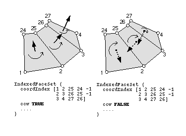
The ElevationGrid, Extrusion, and IndexedFaceSet nodes each have three SFBool fields that provide hints about the shape such as whether the shape contains ordered vertices, whether the shape is solid, and whether the shape contains convex faces. These fields are ccw, solid, and convex, respectively.
The ccw field defines the ordering of the vertex coordinates of the geometry with respect to user-given or automatically generated normal vectors used in the lighting model equations. If ccw is TRUE, the normals shall follow the right hand rule; the orientation of each normal with respect to the vertices (taken in order) shall be such that the vertices appear to be oriented in a counterclockwise order when the vertices are viewed (in the local coordinate system of the Shape) from the opposite direction as the normal. If ccw is FALSE, the normals shall be oriented in the opposite direction. If normals are not generated but are supplied using a Normal node, and the orientation of the normals does not match the setting of the ccw field, results are undefined.
See Figure 2-3 for an illustration of the effect of the ccw field on an IndexedFaceSet's default normals.
The solid field determines whether one or both sides of each polygon shall be displayed. If solid is FALSE, each polygon shall be visible regardless of the viewing direction (i.e., no backface culling shall be done, and two-sided lighting shall be performed to illuminate both sides of lit surfaces). If solid is TRUE, the visibility of each polygon shall be determined as follows: Let V be the position of the viewer in the local coordinate system of the geometry. Let N be the geometric normal vector of the polygon, and let P be any point (besides the local origin) in the plane defined by the polygon's vertices. Then if (V dot N) - (N dot P) is greater than zero, the polygon shall be visible; if it is less than or equal to zero, the polygon shall be invisible (backface culled).
The convex field indicates whether all polygons in the shape are convex (TRUE). A polygon is convex if it is planar, does not intersect itself, and all of the interior angles at its vertices are less than 180 degrees. Non-planar and self-intersecting polygons may produce undefined results even if the convex field is FALSE.
It is recommended that you avoid creating nonplanar polygons, even though it is legal within VRML. Since the VRML specification does not specify a triangulation scheme, each browser may triangulate differently. This is especially important when creating objects with a low number of polygons; the triangulation is more apparent. One way to avoid this issue is to generate triangles rather than polygons.
Default field values throughout VRML were chosen to optimize for rendering speed. You should try to create objects that adhere to the following defaults: solid TRUE, convex TRUE, and ccw TRUE. You should be especially careful if you provide normals for your objects that the orientation of the normals match the setting of the ccw field; getting this wrong can result in completely black surfaces in some renderers.
It might be simpler if VRML simply had backface and twoSide flags to control polygon backface removal and two-sided lighting (although another flag to indicate the orientation of polygons would still be needed). However, the hints chosen allow implementations to perform these common optimizations without tying the VRML specification to any particular rendering technique. Backface removal, for example, should not be done if using a renderer that can display reflections.
The creaseAngle field, used by the ElevationGrid, Extrusion, and IndexedFaceSet nodes, affects how default normals are generated. If the angle between the geometric normals of two adjacent faces is less than the crease angle, normals shall be calculated so that the faces are smooth-shaded across the edge; otherwise, normals shall be calculated so that a lighting discontinuity across the edge is produced. For example, a crease angle of .5 radians means that an edge between two adjacent polygonal faces will be smooth shaded if the geometric normals of the two faces form an angle that is less than .5 radians. Otherwise, the faces will appear faceted. Crease angles must be greater than or equal to 0.0.
See figure 2-4 for an illustration of the effects of the creaseAngle field. Polgon face a and polyon face b have angle between their normals that is less than the specified creaseAngle and thus the generated normals at the vertex shared by a and b (Na and Nb) are identical and produce a smooth surface effect. However, the angle between the normals of polygon c and d is greater than the specified creaseAngle and thus the generated normals (Nc and Nd) produce a faceted surface effect.
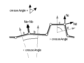
Specifying a single crease angle for each of your shapes instead of specifying individual normals at each of its vertices is a great bandwidth-saving technique. For almost every shape there is an appropriate crease angle that will produce smooth surfaces and sharp creases in the appropriate places.
An almost infinite number of geometry nodes could have been added to VRML 2.0. It was not easy to decide what should be included and what should be excluded, and additions were kept to a minimum because an abundance of geometry types makes it more difficult to write tools that deal with VRML files. A new geometry was likely to be included if it
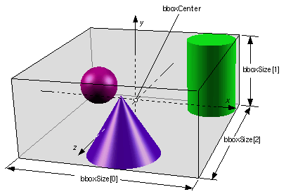
Several of the nodes include a bounding box specification comprised of two fields, bboxSize and bboxCenter. A bounding box is a rectangular parallelepiped of dimension bboxSize centred on the location bboxCenter in the local coordinate system. This is typically used by grouping nodes to provide a hint to the browser on the group's approximate size for culling optimizations. The default size for bounding boxes (-1, -1, -1) indicates that the user did not specify the bounding box and the browser is to compute it or assume the most conservative case. A bboxSize value of (0, 0, 0) is valid and represents a point in space (i.e., an infinitely small box). Specified bboxSize field values shall be >= 0.0 or equal to (-1, -1, -1). The bboxCenter fields specify a position offset from the local coordinate system.
Why does VRML use axis-aligned bounding boxes instead of some other bounding volume representation such as bounding spheres? The choice was fairly arbitrary, but tight bounding boxes are very easy to calculate, easy to transform, and they have a better "worst-case" behavior than bounding spheres (the bounding box of a spherical object encloses less empty area than the bounding sphere of a long, skinny object).
The bboxCenter and bboxSize fields may be used to specify a maximum possible bounding box for the objects inside a grouping node (e.g., Transform). These are used as hints to optimize certain operations such as determining whether or not the group needs to be drawn. If the specified bounding box is smaller than the true bounding box of the group, results are undefined. The bounding box should be large enough to contain completely the effects of all sound and light nodes that are children of this group. If the size of this group may change over time due to animating children, then the bounding box must also be large enough to contain all possible animations (movements). The bounding box should typically be the union of the group's children bounding boxes; it should not include any transformations performed by the group itself (i.e., the bounding box is defined in the local coordinate system of the group).
The bboxCenter and bboxSize fields may be used to specify a maximum possible bounding box for the objects inside a grouping node (e.g., Transform). These are used as hints to optimize certain operations such as determining whether or not the group needs to be drawn. If the specified bounding box is smaller than the true bounding box of the group, results are undefined. The bounding box shall be large enough to completely contain the effects of all sound and light nodes that are children of this group. If the size of this group changes over time due to animating children or due to the addition of children nodes, the bounding box shall also be large enough to contain all possible changes. The bounding box shall be large enough to contain the union of the group's children's bounding boxes; it shall not include any transformations performed by the group itself (i.e., the bounding box is defined in the local coordinate system of the group).
See the illustration in Figure 2-5 of a grouping node and its bounding box. In this figure the grouping node contains three shapes: a Cone, a Cylinder, and a Sphere. The bounding box size is chosen to enclose the three geometries completely.
Prespecified bounding boxes help browsers do two things: avoid loading parts of the world from across the network and avoid simulating parts of the world that can't be sensed. Both of these rely on the "out-of-sight-out-of-mind" principle: If the user cannot see or hear part of the world, then there's no reason for the VRML browser to spend any time loading or simulating that part of the world.
For many operations, a VRML browser can automatically calculate bounding volumes and automatically optimize away parts of the scene that aren't perceptible. For example, even if you do not prespecify bounding boxes in your VRML world, browsers can compute the bounding box for each part of the world and then avoid drawing the parts of the scene that are not visible. Since computing a bounding box for part of the world is almost always faster than drawing it, if parts of the world are not visible (which is usually the case), then doing this "render culling" will speed up the total time it takes to draw the world. Again, this can be done automatically and should not require that you prespecify bounding boxes.
However, some operations cannot be automatically optimized in this way because they suffer from a "chicken-and-egg" problem: The operation could be avoided if the bounding box is known, but to calculate the bounding box requires that the operation be -performed!
Delaying loading parts of the world (specified using either the Inline node or an EXTERNPROTO definition) that are not perceptible falls into this category. If the bounding box of those parts of the world is known, then the browser will know if those parts of the world might be perceptible. However, the bounding box cannot be automatically calculated until those parts of the world are loaded.
One possible solution would be to augment the standard Web protocols (such as HTTP) to support a "get bounding box" request; then, instead of asking for an entire .wrl file to be loaded, a VRML browser could just ask the server to send it the bounding box of the .wrl file. Perhaps, eventually, Web servers will support such requests, but until VRML becomes ubiquitous it is unlikely there will be enough demand on server vendors to add VRML-specific features. Also, often the network bottleneck is not transferring the data, but just establishing a connection with a server, and this solution could worsen that bottleneck since it might require two connections (once for the bounding box information and once for the actual data) for each perceptible part of the world.
Extending Web servers to give bounding box information would not help avoiding simulating parts of the world that aren't perceptible, either. Imagine a VRML world that contained a toy train set with a train that constantly traveled around the tracks. If the user is not looking at the train set, then there is no reason the VRML browser should spend any time simulating the movement of the train (which could be arbitrarily complicated and might involve movement of the train's wheels, engine, etc.). But the browser can't determine if the train is visible unless it knows where the train is; and it won't know exactly where the train is unless it has simulated its movement, which is exactly the work we hoped to avoid.
The solution is for the world creator to give the VRML browser some extra information in the form of an assertion about what might possibly happen. In the case of the toy train set, the user can give a maximum possible bounding box for the train that surrounds all the possible movements of the train. Note that if the VRML browser could determine all the possible movements of the train, then it could also do this calculation. However, calculating all possible movements can be very complicated and is often not possible at all because the movements might be controlled by an arbitrary program contained in a Script node. Usually it is much easier for the world creator (whether a computer program or a human being) to tell the browser the maximum possible extent of things.
Note also that the world's hierarchy can be put to very good use to help the browser minimize work. For example, it is common that an object have both a "large" motion through the world and "small" motions of the object's parts (e.g., a toy train moves along its tracks through the world, but may have myriad small motions of its wheels, engine, drive rods, etc.). If the object is modeled this way and appropriate maximum bounding boxes are specified, then a browser may be able to optimize away the simulation of the small motions after it simulates the large motion and determines that the object as a whole cannot be seen.
Once set, maximum bounding boxes cannot be changed. A maximum bounding box specification is an assertion; allowing the assertion to change over time makes implementations that rely on the assertion more complicated. The argument for allowing maximum bounding boxes to be changed is that the world author can often easily compute the bounding box for changing objects and thus offload the VRML browser from the work. However, this would require the VRML browser to execute the code continually to calculate the bounding box. It might be better to extend the notion of a bounding box to the more general notion of a bounding box that is valid until a given time. World authors could give assertions about an object's possible location over a specific interval of time, and the browser would only need to query the world-/creator-defined Script after that time interval had elapsed. In any case, experimentation with either approach is possible by extending a browser with additional nodes defined with the EXTERNPROTO extension mechanism (see Section 2.8, Browser Extensions).
Grouping nodes have a children field that contains a list of nodes (exceptions to this rule are Inline, LOD, and Switch). Each grouping node defines a coordinate space for its children. This coordinate space is relative to the coordinate space of the node of which the group node is a child. Such a node is called a parent node. This means that transformations accumulate down the scene graph hierarchy.
The following node types are grouping nodes:
The following node types are children nodes:
The following node types are not valid as children nodes:
Unlike VRML 1.0, the VRML 2.0 scene graph serves only as a transformation and -spatial-grouping hierarchy. The transformation hierarchy allows the creation of jointed, rigid-body motion figures. The transformation hierarchy is also often used for spatial grouping. Tables and chairs can be defined in their own coordinate systems, grouped to form a set that can be moved around a house, which in turn is defined in its own coordinate system and grouped with other houses to create a neighborhood. Grouping things in this way is not only convenient, it also improves performance in most -implementations.
The VRML 1.0 scene graph also defined an object property hierarchy. For example, a texture property could be placed at any level of the scene hierarchy and could affect an entire subtree of the hierarchy. VRML 2.0 puts all properties inside the hierarchy's lowest level nodes—a texture property cannot be associated with a grouping node; it can only be associated with one or more Shape nodes.
This simplified scene graph structure is probably the biggest difference between VRML 1.0 and VRML 2.0, and was motivated by feedback from several different implementors. Some rendering libraries have a simpler notion of rendering state than VRML 1.0, and the mismatch between these libraries and VRML was causing performance problems and implementation complexity.
VRML 2.0's ability to change the values and topology of the scene graph over time makes it even more critical for the scene graph structure to match existing rendering libraries. It is fairly easy to convert a VRML file to the structure expected by a rendering library once; it is much more difficult to come up with a conversion scheme that efficiently handles a constantly changing scene.
VRML 2.0's simpler structure means that each part of the scene graph is almost completely self-contained. An implementation can render any part of the scene graph if it knows
For example, this makes it much easier for an implementation to render different parts of the scene graph at the same time or to rearrange the order in which it decides to render the scene (e.g., to group objects that use the same texture map, which is faster on some graphics hardware).
All grouping nodes also have addChildren and removeChildren eventIn definitions. The addChildren event appends nodes to the grouping node's children field. Any nodes passed to the addChildren event that are already in the group's children list are ignored. For example, if the children field contains the nodes Q, L and S (in order) and the group receives an addChildren eventIn containing (in order) nodes A, L, and Z, the result is a children field containing (in order) nodes Q, L, S, A, and Z.
The removeChildren event removes nodes from the grouping node's children field. Any nodes in the removeChildren event that are not in the grouping node's children list are ignored. If the children field contains the nodes Q, L, S, A and Z and it receives a removeChildren eventIn containing nodes A, L, and Z, the result is Q, S.
The Inline, Switch and LOD nodes are special group nodes that do not have all of the semantics of the regular grouping nodes (see "3.25 Inline", "3.26 LOD", and "3.46 Switch" for specifics).
The order of a grouping node's children has no effect on the perceivable result; the children can be rearranged and there will be no change to the VRML world. This was a conscious design decision that simplifies the Open Inventor scene graph by eliminating most of the traversal state and enabling easier integration with rendering libraries (very few rendering libraries today support Inventor's rich traversal state). The net effect of this decision is smaller and simpler implementations, but more burden on the author to share attributes in the scene graph. It is important to note that the order of children is deterministic and cannot be altered by the implementation, since Script nodes may access children and assume that the order does not change.
The LOD and Switch nodes are not considered grouping nodes because they have different semantics from the grouping nodes. Grouping nodes display all of their children, and the order of children for a grouping node is unimportant, while Switch and LOD display, at most, one of their "children" and their order is very important.
Note that a variety of node types reference other node types through fields. Some of these are parent-child relationships, while others are not (there are node-specific semantics). Table 2-3 lists all node types that reference other nodes through fields.
| Node Type | Field | Valid Node Types for Field |
|---|---|---|
| Anchor | children | Valid children nodes |
| Appearance | material | Material |
| texture | ImageTexture, MovieTexture, Pixel Texture | |
| Billboard | children | Valid children nodes |
| Collision | children | Valid children nodes |
| ElevationGrid | color | Color |
| normal | Normal | |
| texCoord | TextureCoordinate | |
| Group | children | Valid children nodes |
| IndexedFaceSet | color | Color |
| coord | Coordinate | |
| normal | Normal | |
| texCoord | TextureCoordinate | |
| IndexedLineSet | color | Color |
| coord | Coordinate | |
| LOD | level | Valid children nodes |
| Shape | appearance | Appearance |
| geometry | Box, Cone, Cylinder, ElevationGrid, Extrusion, IndexedFaceSet, IndexedLineSet, PointSet, Sphere, Text | |
| Sound | source | AudioClip, MovieTexture |
| Switch | choice | Valid children nodes |
| Text | fontStyle | FontStyle |
| Transform | children | Valid children nodes |
Shape nodes are illuminated by the sum of all of the lights in the world that affect them. This includes the contribution of both the direct and ambient illumination from light sources. Ambient illumination results from the scattering and reflection of light originally emitted directly by light sources. The amount of ambient light is associated with the individual lights in the scene. This is a gross approximation to how ambient reflection actually occurs in nature.
The VRML lighting model is a gross approximation of how lighting actually occurs in nature. It is a compromise between speed and accuracy, with more emphasis put on speed. A more physically accurate lighting model would require extra lighting calculations and result in slower rendering. VRML's lighting model is similar to those used by current computer graphics software and hardware.
The following node types are light source nodes:
All light source nodes contain an intensity, a color, and an ambientIntensity field. The intensity field specifies the brightness of the direct emission from the light, and the ambientIntensity specifies the intensity of the ambient emission from the light. Light intensity may range from 0.0 (no light emission) to 1.0 (full intensity). The color field specifies the spectral colour properties of the both direct and ambient light emission, as an RGB value.
The intensity field is really a convenience; adjusting the RGB values in the color field appropriately is equivalent to changing the intensity of the light. Or, in other words, the light emitted by a light source is equal to intensity × color. Similarly, setting the on field to FALSE is equivalent to setting the intensity and ambientIntensity fields to zero.
Some photorealistic rendering systems allow light sinks — light sources with a negative intensity. They also sometimes support intensities of greater than 1.0. Interactive rendering libraries typically don't support those features, and since VRML is designed for interactive playback the specification only defines results for values in the 0.0 to 1.0 range.
PointLight and SpotLight illuminate all objects in the world that fall within their volume of lighting influence regardless of location within the file. PointLight defines this volume of influence as a sphere centred at the light (defined by a radius). SpotLight defines the volume of influence as a solid angle defined by a radius and a cutoff angle. DirectionalLights illuminate only the objects descended from the light's parent grouping node, including any descendent children of the parent grouping nodes.
A good light source specification is difficult to design. There are two primary problems: first, how to scope light sources so that the "infinitely scalable" property of VRML is maintained and second, how to specify both the light's coordinate system and the objects that it illuminates.
If light sources are not scoped in some way, then a VRML world that contains a lot of light sources requires that all of the light sources be taken into account when drawing any part of the world. By scoping light sources, only a subset of the lights in the world ever need to be considered, allowing worlds to grow arbitrarily large.
For PointLight and SpotLight, the scoping problem is addressed by giving them a radius of effect. Nothing outside of the radius is affected by the light. Implementors will be forced to approximate this ideal behavior, because current interactive rendering libraries typically only support light attenuation and do not support a fixed radius beyond which no light falls. Content creators should choose attenuation constants such that the intensity of a light source is very close to zero at the cutoff radius (or, alternatively, choose a cutoff radius based on the attenuation constants).
A directional light sends parallel rays of light from a particular direction. Attenuation makes no sense for a directional light, since the light is not emanating from any particular location. Therefore, it makes no sense to try to specify a cutoff radius or any other spatial scoping. Instead, DirectionalLight is scoped by its position in the scene hierarchy, illuminating only sibling geometry (geometry underneath the same Group or Transform as the DirectionalLight). Although unrealistic, defining DirectionalLight this way allows efficient implementations and allows content creators a reasonable amount of control over the lighting of their virtual worlds.
The second problem--defining the light's coordinate system separately from which objects the light illuminates--is addressed by the cutoff radius field of PointLight and SpotLight. Their position in the scene hierarchy determines only their location in space; they illuminate all objects that fall within the cutoff radius of that location. This makes implementing them more difficult, since the position of all point lights and spot lights must be known before anything is drawn. Current interactive rendering hardware and software make it even more difficult, since they support only a small number of light sources (e.g., eight) at once. Implementors can either turn light sources on and off as different pieces of geometry are drawn or can just use a few of the light sources and ignore the rest. The VRML 2.0 specification requires only that eight simultaneous light sources be supported (see Chapter 5, Conformance and Minimum Support Requirements). World creators should bear this in mind and minimize the number of light sources turned on at any given time.
DirectionalLight does not attempt to decouple its position in the scene hierarchy from the objects that it illuminates. That can result in unrealistic behavior. For example, a directional light that illuminates everything inside a room will not illuminate an object that travels into the room unless that object is in the room's part of the scene hierarchy, and an object that moves outside the room will continue to be lit by the directional light until it is moved outside of the room Group. A better solution for moving objects around the scene hierarchy as their position in the virtual world changes may eventually be needed, but until then content creators will have to use existing mechanisms to get their desired results (e.g., by knowing the Group for each room in their virtual world and using addChildren/removeChildren events to move objects from one Group to another as they travel around the virtual world).
The following nodes types are sensor nodes:
Sensors are children nodes in the hierarchy and therefore may be parented by grouping nodes as described in "2.6.5 Grouping and children nodes."
They are called sensors because they sense changes to something. Sensors detect changes to the state of an input device (TouchSensor, CylinderSensor, Plane-Sensor, SphereSensor), changes in time (TimeSensor), or changes related to the motion of the viewer or objects in the virtual world (ProximitySensor, VisibilitySensor, and Collision group).
Some often-requested features that did not make it into VRML 2.0 could be expressed as new sensor types. These are object-to-object collision detection, support for 3D input devices, and keyboard support.
Viewer-object collision detection is supported by the Collision group, but object-to-object collision detection is harder to implement and much harder to specify. Only recently have robust, fast implementations for detecting collisions between any two objects in an arbitrary virtual world become available, and efficient algorithms for object-to-object collision detection is still an area of active research. Even assuming fast, efficient algorithms are widely available and reasonably straightforward to implement, it is difficult to specify precisely which nodes should be tested for collisions and what events should be produced when they collide. Designing a solution that works for a particular application (e.g., a game) is easy; designing a general solution that works for a wide range of applications is much harder.
Support for input devices like 3D mice, 3D joysticks, and spatial trackers was also an often-requested feature. Ideally, a world creator would describe the desired interactions at a high level of abstraction so that users could use any input device they desired to interact with the world. There might be a Motion3DSensor that gives 3D positions and orientations in the local coordinate system, driven by whatever input device the user happened to be using.
In practice, however, creating an easy-to-use experience requires knowledge of the capabilities and limitations of the input device being used. This is true even in the well-researched world of 2D input devices; drawing applications treat a pressure-sensitive tablet differently than a mouse.
One alternative to creating a general sensor to support 3D input devices was to create many different sensors, one for each different device or class of devices. There were two problems with doing this: First, the authors of the VRML 2.0 specification are not experts in the subtleties of all of the various 3D input device technologies and second, it isn't clear that many world creators would use these new sensors since they would restrict the use of their worlds to people that had the appropriate input device (a very small percentage of computer users). It is expected that prototype extensions that -support 3D input devices will be available and proposed for future revisions of the VRML specification.
Unlike 3D input devices, keyboards are ubiquitous in the computing world. However, there is no KeyboardSensor in the VRML 2.0 standard. Virtual reality purists might argue that this is a good thing since keyboards have no place in immersive virtual worlds (and we should have SpeechSensor and FingerSensor instead), but that isn't the reason for its absence from the VRML specification. During the process of designing KeyboardSensor several difficult design issues arose for which no satisfactory solution was found. In addition, VRML is not designed to be a stand-alone, do-everything standard. It was designed to take advantage of the other standards that have been defined for the Internet whenever possible, such as JPEG, MPEG, Java, HTTP, and URLs.
The simplest keyboard support would be reporting key-press and key-release events. For example, a world creator might want a platform to move up while a certain key is pressed and to move down when another key is pressed. Or, different keys on the keyboard might be used to "teleport" the user to different locations in the world. Adding support for a single KeyboardSensor of this type in a world would be straightforward, but designing for just a single KeyboardSensor goes against the composability design goals for VRML. It also duplicates functionality that is better left to other standards. For example, Java defines a set of keyboard events that may be received by a Java applet. Rather than wasting time duplicating the functionality of Java inside VRML, defining a general communication mechanism between a Java applet and a VRML world will give this functionality and much more.
Java also defines textArea and textField components that allow entry of arbitrary text strings. Designing the equivalent functionality for text input inside a 3D world (e.g., fill-in text areas on the walls of a room) would require the definition of a 2D windowing system inside the 3D world. Issues such as input methods for international characters, keyboard focus management, and a host of other issues would have to be reimplemented if a VRML solution were invented. Again, rather than wasting time duplicating the functionality of existing windowing systems, it might be better to define a general way of embedding existing 2D standards into the 3D world. Experimentation along these lines is certainly possible using the current VRML 2.0 standard. The ImageTexture node can point to arbitrary 2D content, and although only the PNG and JPEG image file formats are required, browser implementors could certainly support ImageTexture nodes that pointed to Java applets. They could even map mouse and keyboard events over the texture into the 2D coordinate space of the Java applet to support arbitrary interaction with Java applets pasted onto objects in a 3D world.
Each type of sensor defines when an event is generated. The state of the scene graph after several sensors have generated events shall be as if each event is processed separately, in order. If sensors generate events at the same time, the state of the scene graph will be undefined if the results depend on the ordering of the events.
Events generated by sensor nodes are given time stamps that specify exactly when the event occurred. These time stamps should be the exact or ideal time that the event occurred and not the time that the event happened to be generated by the sensor. For example, the time stamp for a TouchSensor's isActive TRUE event generated by clicking the mouse should be the actual time when the mouse button was pressed, even if it takes a few microseconds for the mouse-press event to be delivered to the VRML application. This isn't very important if events are handled in isolation, but can be critical in cases when the sequence or timing of multiple events is important. For example, the world creator might set a double-click threshold on an object. If the user clicks the mouse (or, more generally, activates the pointing device) twice rapidly enough, an animation is started. The browser may happen to receive one click just before it decides to rerender the scene and the other click after it is finished rendering the scene. If it takes the browser longer to render the scene than the double-click threshold and the browser time stamps the click events based on when it gets around to processing them, then the double-click events will be lost and the user will be very frustrated. Happily, modern operating and windowing systems are multithreaded and give the raw device events reasonably accurate time stamps that can be retrieved and used by VRML browsers.
It is possible to create dependencies between various types of sensors. For example, a TouchSensor may result in a change to a VisibilitySensor node's transformation, which in turn may cause the VisibilitySensor node's visibility status to change.
The following two sections classify sensors into two categories: environmental sensors and pointing-device sensors.
If you create a paradoxical or indeterministic situation, your world may behave differently on different VRML browsers. Achieving identical (or at least almost-identical) results on different implementations is the primary reason for defining a VRML specification, so a lot of thought was put into designs that removed any possibilities of indeterministic results. For example, two sensors that generated events at exactly the same time could be given a well-defined order, perhaps based on which was created first or their position in the scene graph. Requiring implementations to do this was judged to be unreasonable, because different implementations will have different strategies for delaying the loading of different parts of the world (affecting the order in which nodes are created) and because the scene graph ordering can change over time. The overhead required to make all possible worlds completely deterministic isn't worth the runtime costs. Indeterministic situations are easy to avoid, can be detected and reported at run-time (so the world creator knows that they have a problem), and are never useful.
The ProximitySensor detects when the user navigates into a specified region in the world. The ProximitySensor itself is not visible. The TimeSensor is a clock that has no geometry or location associated with it; it is used to start and stop time-based nodes such as interpolators. The VisibilitySensor detects when a specific part of the world becomes visible to the user. The Collision grouping node detects when the user collides with objects in the virtual world. Pointing-device sensors detect user pointing events such as the user clicking on a piece of geometry (i.e., TouchSensor). Proximity, time, collision, and visibility sensors are each processed independently of whether others exist or overlap.
The following node types are pointing-device sensors:
A pointing-device sensor is activated when the user locates the pointing device over geometry that is influenced by that specific pointing-device sensor. Pointing-device sensors have influence over all geometry that is descended from the sensor's parent groups. In the case of the Anchor node, the Anchor node itself is considered to be the parent group. Typically, the pointing-device sensor is a sibling to the geometry that it influences. In other cases, the sensor is a sibling to groups which contain geometry (i.e., are influenced by the pointing-device sensor).
The appearance properties of the geometry do not affect activation of the sensor. In particular, transparent materials or textures shall be treated as opaque with respect to activation of pointing-device sensors.
It is a little bit strange that pointing device sensors sense hits on all of their sibling geometry. Geometry that occurs before the pointing device sensor in the children list is treated exactly the same as geometry that appears after the sensor in the children list. This is a consequence of the semantics of grouping nodes. The order of children in a grouping node is irrelevant, so the position of a pointing device sensor in the children list does not matter.
Adding a sensor MFNode field to the grouping nodes as a place for sensors (instead of just putting them in the children field) was considered, but rejected because it added complexity to the grouping nodes, was less extensible, and produced little benefit.
For a given user activation, the lowest, enabled pointing-device sensor in the hierarchy is activated. All other pointing-device sensors above the lowest, enabled pointing-device sensor are ignored. The hierarchy is defined by the geometry node over which the pointing-device sensor is located and the entire hierarchy upward. If there are multiple pointing-device sensors tied for lowest, each of these is activated simultaneously and independently, possibly resulting in multiple sensors activating and generating output simultaneously. This feature allows combinations of pointing-device sensors (e.g., TouchSensor and PlaneSensor). If a pointing-device sensor appears in the transformation hierarchy multiple times (DEF/USE), it must be tested for activation in all of the coordinate systems in which it appears.
If a pointing-device sensor is not enabled when the pointing-device button is activated, it will not generate events related to the pointing device until after the pointing device is deactivated and the sensor is enabled (i.e., enabling a sensor in the middle of dragging does not result in the sensor activating immediately). Note that some pointing devices may be constantly activated and thus do not require a user to activate.
There's an intentional inconsistency between the behavior of the pointing device sensors and the proximity, visibility, and time sensors. The pointing device sensors follow a "lowest-ones-activate" policy, but the others follow an "all-activate" policy. These different policies were chosen based on expected usage.
A TouchSensor, for example, is expected to be used for things like push-buttons in the virtual world. Hierarchical TouchSensors might be used for something like a TV set that had both buttons inside it to turn it on and off, change the channel, and so forth, but also had a TouchSensor on the entire TV that activated a hyperlink (perhaps bringing up the Web page for the product being advertised on the virtual TV). In this case, it would be inconvenient if the hyperlink was also activated when the channel-changing buttons were pressed.
On the other hand, for most expected uses of proximity and visibility sensors it is more convenient if they act completely independently of each other. In either case, the opposite behavior is always achievable by either rearranging the scene graph or enabling and disabling sensors at the right times.
More complicated policies for the pointing device sensors were considered, giving the world creator control over whether or not events were processed and/or propagated upward at each sensor. However, the simpler policy was chosen because it had worked well in the Open Inventor toolkit and because any desired effect can be achieved by rearranging the position of sensors in the scene graph and/or using a script to enable and disable sensors.
The Anchor node is considered to be a pointing-device sensor when trying to determine which sensor (or Anchor node) to activate. For example, in the following file a click on Shape3 is handled by SensorD, a click on Shape2 is handled by SensorC and the AnchorA, and a click on Shape1 is handled by SensorA and SensorB:
    Group {
      children [
        DEF Shape1  Shape       { ... }
        DEF SensorA TouchSensor { ... }
        DEF SensorB PlaneSensor { ... }
        DEF AnchorA Anchor {
          url "..."
          children [
            DEF Shape2  Shape { ... }
            DEF SensorC TouchSensor { ... }
            Group {
              children [
                DEF Shape3  Shape { ... }
                DEF SensorD TouchSensor { ... }
              ]
            }
          ]
        }
      ]
    }
Drag sensors are a subset of pointing-device sensors. There are three types of drag sensors: CylinderSensor, PlaneSensor, and SphereSensor. Drag sensors have two eventOuts in comon, trackPoint_changed and <value>_changed. These eventOuts send events for each movement of the activated pointing device according to their "virtual geometry" (e.g., cylinder for CylinderSensor). The trackPoint_changed eventOut sends the unclamped intersection point of the bearing with the drag sensor's virtual geometry. The <value>_changed eventOut sends the sum of the relative change since activation plus the sensor's offset field. The type and name of <value>_changed depends on the drag sensor type: rotation_changed for CylinderSensor, translation_changed for PlaneSensor, and rotation_changed for SphereSensor.
The TouchSensor and the drag sensors map a 2D pointing device in the 3D world, and are the basis for direct manipulation of the objects in the virtual world. TouchSensor samples the motion of the pointing device over the surface of an object, PlaneSensor projects the motion of the pointing device onto a 3D plane, and SphereSensor and -CylinderSensor generate 3D rotations from the motion of the pointing device. Their functionality is limited to performing the mapping from 2D into 3D; they must be combined with geometry, transformations, or script logic to be useful. Breaking apart different pieces of functionality into separate nodes does make it more difficult to perform common tasks, but it creates a design that is much more flexible. Features may be combined in endless variations, resulting in a specification with a whole that is greater than the sum of its parts (and, of course, the prototyping mechanism can be used to make the common variations easy to reuse).
To simplify the application of these sensors, each node has an offset and an autoOffset exposed field. When the sensor generates events as a response to the activated pointing device motion, <value>_changed sends the sum of the relative change since the initial activation plus the offset field value. If autoOffset is TRUE when the pointing-device is deactivated, the offset field is set to the sensor's last <value>_changed value and offset sends an offset_changed eventOut. This enables subsequent grabbing operations to accumulate the changes. If autoOffset is FALSE, the sensor does not set the offset field value at deactivation (or any other time).
The original Moving Worlds drag sensors did not have offset or autoOffset fields. This resulted in drag sensors that reset themselves back to zero at the beginning of each use and made it extremely difficult to create the typical case of an accumulating sensor. By adding the offset field, it enables drag sensors to accumulate their results (e.g., translation, rotation) by saving their last <value>_changed in the offset field.
The pointing device controls a pointer in the virtual world. While activated by the pointing device, a sensor will generate events as the pointer moves. Typically the pointing device may be categorized as either 2D (e.g., conventional mouse) or 3D (e.g., wand). It is suggested that the pointer controlled by a 2D device is mapped onto a plane a fixed distance from the viewer and perpendicular to the line of sight. The mapping of a 3D device may describe a 1:1 relationship between movement of the pointing device and movement of the pointer.
The position of the pointer defines a bearing which is used to determine which geometry is being indicated. When implementing a 2D pointing device it is suggested that the bearing is defined by the vector from the viewer position through the location of the pointer. When implementing a 3D pointing device it is suggested that the bearing is defined by extending a vector from the current position of the pointer in the direction indicated by the pointer.
In all cases the pointer is considered to be indicating a specific geometry when that geometry is intersected by the bearing. If the bearing intersects multiple sensors' geometries, only the sensor nearest to the pointer will be eligible for activation.
Interpolator nodes are designed for linear keyframed animation. An interpolator node defines a piecewise-linear function, f(t), on the interval (-infinity, +infinity). The piecewise-linear function is defined by n values of t, called key, and the n corresponding values of f(t), called keyValue. The keys shall be monotonic nondecreasing and are not restricted to any interval. Results are undefined if the keys are nonmonotonic or nondecreasing.
In other words, interpolators are used to perform keyframe animations. You specify a list of keyframe values and times, and the VRML browser will automatically interpolate the "in-betweens." VRML allows only linear interpolation; it does not support spline curve interpolation, which can be found in most commerical animation systems. This limitation was made in order to keep VRML implementations small, fast, and simple. Note that it is possible for authoring systems to use sophisticated spline curves during authoring, but publish the resulting VRML file using the linear interpolators (thus getting the best of both worlds). You may find that it is necessary to specify a lot of keyframes to produce smooth or complex animations.
Note that there are several different types of interpolators; each one animates a different field type. For example, the PositionInterpolator is used to animate an object's position (i.e., Transform node's translation field) along a motion path (defined by keyValue). To produce typical animated object motion, you can employ both a Position-Interpolator and an OrientationInterpolator. The PositionInterpolator moves the object along a motion path, while the OrientationInterpolator rotates the object as it moves.
Remember that TimeSensor outputs fraction_changed events in the 0.0 to 1.0 range, and that interpolator nodes routed from TimeSensors should restrict their key field values to the 0.0 to 1.0 range to match the TimeSensor output and thus produce a full interpolation sequence.
An interpolator node evaluates f(t) given any value of t (via the set_fraction eventIn) as follows: Let the n keys k0, k1, k2, ..., kn-1 partition the domain (-infinity, +infinity) into the n+1 subintervals given by (-infinity, k0), [k0, k1), [k1, k2), ... , [kn-1, +infinity). Also, let the n values v0, v1, v2, ..., vn-1 be the values of an unknown function, F(t), at the associated key values. That is, vj = F(kj). The piecewise-linear interpolating function, f(t), is defined to be
     f(t) = v0, if t < k0,
          = vn-1, if t > kn-1,
          = vi, if t = ki for some value
            of i, where -1 < i < n,
          = linterp(t, vj, vj+1), if kj < t < kj+1

     where linterp(t,x,y) is the linear interpolant,
     and -1 < j < n-1.
The third conditional value of f(t) allows the defining of multiple values for a single key, (i.e., limits from both the left and right at a discontinuity in f(t)). The first specified value is used as the limit of f(t) from the left, and the last specified value is used as the limit of f(t) from the right. The value of f(t) at a multiply defined key is indeterminate, but should be one of the associated limit values.
The following node types are interpolator nodes, each based on the type of value that is interpolated:
All interpolator nodes share a common set of fields and semantics:
    eventIn      SFFloat      set_fraction
    exposedField MFFloat      key           [...]
    exposedField MF<type>     keyValue      [...]
    eventOut     [S|M]F<type> value_changed
The type of the keyValue field is dependent on the type of the interpolator (e.g., the ColorInterpolator's keyValue field is of type MFColor).
Creating new field types that are more convenient for animation keyframes was considered. This led to thinking about a syntax to create arbitrary new field types. For example, the keyframes for a PositionInterpolator could be defined as M[SFFloat,SFVec3f] (any number of pairs consisting of a float and a vec3f). An SFVec3f might be defined as [SFFloat, SFFloat, SFFloat]. However, creating an entire data type description language to solve what is only a minor annoyance would have had major ramifications on the rest of VRML and was judged to be gratuitous engineering.
The set_fraction eventIn receives an SFFloat event and causes the interpolator function to evaluate, resulting in a value_changed eventOut with the same timestamp as the set_fraction event.
Restricting interpolators to do linear interpolation was controversial, because using curves to do motion interpolation is common. However, there was no single, obvious choice for a curve representation and it seemed unlikely that a technical discussion would be able to resolve the inevitable debate over which curve representation is best. Because simple linear interpolation would be needed even if nonlinear interpolation was part of the specification, and because any nonlinear interpolation can be linearly approximated with arbitrary precision, only linear interpolators made it into the VRML 2.0 specification.
If you are faced with the task of translating an animation curve into VRML's linear interpolators, you have three choices. You can choose a temporal resolution and tessellate the curve into a linear approximation, balancing the quality of the approximation against the size of the resulting file. Better yet, give the user control over the quality versus size trade-off.
Or you can write a script that performs this tessellation when the VRML file is read, put it into an appropriate prototype (which will contain an empty interpolator and the script, with an initialize() method that fills in the fields of the interpolator based on the curve's parameters), and write out the curve representation directly into the VRML file (as fields of prototype instances). Bandwidth requirements will be much smaller since the PROTO definition only needs to be sent once and the untessellated curve parameters will be much smaller than the linear approximation. Animations implemented this way may still require significant memory resources, however, since the tessellation is performed at start-up and stored in memory.
You can also write a script that directly implements the mathematics of the curve interpolation, and put that into a prototype. In fact, all of the linear interpolators defined as part of the VRML standard can be implemented as prototyped Script nodes. The reason they are part of the standard is to allow implementations to create highly optimized interpolators, since they are very common. Therefore, if you want your animations to be executed as quickly as possible, you should tessellate the animation curve (preferably after it has been downloaded, as described in the previous paragraph) and put the result in an interpolator. However, if you want to minimize memory use or maximize the quality of the animation, you should write a script that takes in set_fraction events and computes appropriate value_changed events directly.
Four of the six interpolators output a single-value field to value_changed. Each value in the keyValue field corresponds in order to the parameter value in the key field. Results are undefined if the number of values in the key field of an interpolator is not the same as the number of values in the keyValue field.
CoordinateInterpolator and NormalInterpolator send multiple-value results to value_changed. In this case, the keyValue field is an n x m array of values, where n is the number of values in the key field and m is the number of values at each keyframe. Each m values in the keyValue field correspond, in order, to a parameter value in the key field. Each value_changed event shall contain m interpolated values. Results are undefined if the number of values in the keyValue field divided by the number of values in the key field is not a positive integer.
If an interpolator node's value eventOut is read (e.g., get_value( )) before it receives any inputs, keyValue[0] is returned if keyValue is not empty. If keyValue is empty (i.e., [ ]), the initial value for the eventOut type is returned (e.g., (0, 0, 0) for SFVec3f); see "Chapter 4, Fields and Events Reference" for event default values.
The location of an interpolator node in the transformation hierarchy has no effect on its operation. For example, if a parent of an interpolator node is a Switch node with whichChoice set to -1 (i.e., ignore its children), the interpolator continues to operate as specified (receives and sends events).
The spatial hierarchy of grouping nodes in the scene graph has nothing to do with the logical hierarchy formed by ROUTE statements. Interpolator (and Script) nodes have no particular location in the virtual world, so their position in the spatial hierarchy is irrelevant. You can make them the child of whichever grouping node is convenient or put them all at the end of your VRML file just before all the ROUTE statements.
AudioClip, MovieTexture, and TimeSensor are time-dependent nodes that activate and deactivate themselves at specified times. Each of these nodes contains the exposedFields: startTime, stopTime, and loop, and the eventOut: isActive. The exposedField values are used to determine when the container node becomes active or inactive. Also, under certain conditions, these nodes ignore events to some of their exposedFields. A node ignores an eventIn by not accepting the new value and not generating an eventOut_changed event. In this section, an abstract time-dependent node can be any one of AudioClip, MovieTexture, or TimeSensor.
AudioClip and MovieTexture could have been designed to be driven by a TimeSensor (like the interpolator nodes) instead of having the startTime, and so forth, controls. However, that would have caused several implementation difficulties. Playback of sound and movies is optimized for continuous, in-order play; multimedia systems often have specialized hardware to deal with sound and (for example) MPEG movies. Efficiently implementing the AudioClip and MovieTexture nodes is much harder if those nodes do not know the playback speed, whether or not the sound/movie should be repeated, and so on. In addition, sounds and movies may require "preroll" time to prepare to playback; this is possible only if the AudioClip or MovieTexture know their start time. In this case, separating out the time-generation functionality, although it would make a more flexible system (playing movies backward by inverting the fraction_changed events coming from the TimeSensor going to a MovieTexture would be possible, for example), it would make it unacceptably hard to implement efficiently (it is difficult to play an MPEG movie backward efficiently because of the frame-to-frame compression that is done, for example).
Time-dependent nodes can execute for 0 or more cycles. A cycle is defined by field data within the node. If, at the end of a cycle, the value of loop is FALSE, execution is terminated (see below for events at termination). Conversely, if loop is TRUE at the end of a cycle, a time-dependent node continues execution into the next cycle. A time-dependent node with loop TRUE at the end of every cycle continues cycling forever if startTime >= stopTime, or until stopTime if stopTime > startTime.
Unless you set the stopTime field, a time-dependent node either cycles once (if loop is FALSE) or plays over and over again (if loop is TRUE). For MovieTexture, one cycle corresponds to displaying the movie once; for AudioClip, playing the sound once; for TimeSensor, generating fraction_changed events that go from 0.0 to 1.0 once.
The startTime, stopTime, and loop fields are generally all you need to accomplish simple tasks. StartTime is simply the time at which the animation or sound or movie should start. StopTime was named interruptTime in a draft version of the VRML specification; it allows you to stop the animation/sound/movie while it is playing. And loop just controls whether or not the animation/sound/movie is repeated.
A time-dependent node generates an isActive TRUE event when it becomes active and generates an isActive FALSE event when it becomes inactive. These are the only times at which an isActive event is generated. In particular, isActive events are not sent at each tick of a simulation.
A time-dependent node is inactive until its startTime is reached. When time now becomes greater than or equal to startTime, an isActive TRUE event is generated and the time-dependent node becomes active (now refers to the time at which the browser is simulating and displaying the virtual world). When a time-dependent node is read from a file and the ROUTEs specified within the file have been established, the node should determine if it is active and, if so, generate an isActive TRUE event and begin generating any other necessary events. However, if a node would have become inactive at any time before the reading of the file, no events are generated upon the completion of the read.
An active time-dependent node will become inactive when stopTime is reached if stopTime > startTime. The value of stopTime is ignored if stopTime <= startTime. Also, an active time-dependent node will become inactive at the end of the current cycle if loop is FALSE. If an active time-dependent node receives a set_loop FALSE event, execution continues until the end of the current cycle or until stopTime (if stopTime > startTime), whichever occurs first. The termination at the end of cycle can be overridden by a subsequent set_loop TRUE event.
Any set_startTime events to an active time-dependent node are ignored. Any set_stopTime events where stopTime <= startTime, to an active time-dependent node are also ignored. A set_stopTime event where startTime < stopTime <= now sent to an active time-dependent node results in events being generated as if stopTime has just been reached. That is, final events, including an isActive FALSE, are generated and the node becomes inactive. The stopTime_changed event will have the set_stopTime value. Other final events are node-dependent (c. f., TimeSensor).
To get precise, reproducible behavior, there are a lot of edge conditions that must be handled the same way in all implementations. Creating a concise, precise specification that defined the edge cases was one of the most difficult of the VRML 2.0 design tasks.
One problem was determining how to handle set_stopTime events with values that are in the past. In theory, if the world creator sends a TimeSensor a set_stopTime "yesterday" event, they are asking to see the state of the world as if the time sensor had stopped yesterday. And, theoretically, a browser could resimulate the world from yesterday until today, replaying any events and taking into account the stopped time sensor. However, requiring browsers to interpret events that occurred in the past is unreasonable; so, instead, set_stopTime events in the past are either ignored (if stopTime < startTime) or are reinterpreted to mean "now."
A time-dependent node may be restarted while it is active by sending a set_stopTime event equal to the current time (which will cause the node to become inactive) and a set_startTime event, setting it to the current time or any time in the future. These events will have the same time stamp and should be processed as set_stopTime, then set_startTime to produce the correct behaviour.
To pause and then restart an animation, do the following in a script: Set the stopTime to now to pause the animation. To restart, you must adjust both the startTime and the stopTime of the animation. Advance the startTime by the amount of time that the animation has been paused so that it will continue where it left off. This is easily calculated as startTime = startTime + now - stopTime (where now is the time stamp of the event that causes the animation to be restarted). Set the stopTime to zero or any other value less than or equal to startTime, so that it is ignored and the animation restarts.
There are implicit dependencies between the fields of time-dependent nodes. If a time-dependent node receives several events with exactly the same time stamp, these dependencies force the events to be processed in a particular order. For example, if, at time T, a TimeSensor node receives both a set_active FALSE and a set_startTime event (both with time stamp T), the node must behave as if the set_active event is processed first and must not start playing. Similarly, set_stopTime events must be processed before set_startTime events with the same time stamp.
Set_startTime events are ignored if a time-dependent node is active, because doing so makes writing robust animations much easier. For example, if you have a button (a touch sensor and some geometry) that starts an animation, you usually want the animation to finish playing, even if the user presses the button again while the animation is playing. You can easily get the other behavior by setting both stopTime and startTime when the button is pressed. If set_startTime events were not ignored when the node was active, then achieving "play-to-completion" behavior would require use of a Script to manage set_startTime events.
The default values for each of the time-dependent nodes are specified such that any node with default values is already inactive (and, therefore, will generate no events upon loading). A time-dependent node can be defined such that it will be active upon reading by specifying loop TRUE. This use of a non-terminating time-dependent node should be used with caution since it incurs continuous overhead on the simulation.
If you want your worlds to be scalable, everything in them should have a well-defined scope in space or time. Spatial scoping means specifying bounding boxes that represent the maximum range of an object's motion whenever possible, and arranging objects in spatial hierarchies. Temporal scoping means giving any animations well-defined starting and ending times. If you create an animation that is infinitely long--a windmill turning in the breeze, perhaps--you should try to specify its spatial scope, so that the browser can avoid performing the animation if that part of space cannot be seen.
The Background, Fog, NavigationInfo, and Viewpoint nodes have the unique behaviour that only one of each type can be bound (i.e., affecting the user's experience) at any instant in time. The browser shall maintain an independent, separate stack for each type of binding node. Each of these nodes includes a set_bind eventIn and an isBound eventOut. The set_bind eventIn is used to move a given node to and from its respective top of stack. A TRUE value sent to the set_bind eventIn moves the node to the top of the stack; sending a FALSE value removes it from the stack. The isBound event is output when a given node is:
That is, isBound events are sent when a given node becomes or ceases to be the active node. The node at the top of stack, (the most recently bound node), is the active node for its type and is used by the browser to set the world state. If the stack is empty (i.e., either the file has no binding nodes for a given type or the stack has been popped until empty), the default field values for that node type are used to set world state. The results are undefined if a multiply instanced (DEF/USE) bindable node is bound.
In general, you should avoid creating multiple instances of bindable nodes (i.e., don't USE bindable nodes). Results are undefined for multi-instanced bindable nodes because the effects of binding a Background, Fog, or Viewpoint node depend on the coordinate space in which it is located. If it is multi-instanced, then it (probably) exists in multiple coordinate systems. For example, consider a Viewpoint node that is multi-instanced. The first instance (DEF VIEW) specifies it at the origin and the second instance (USE VIEW) translates it to (10,10,10):
        # Create 1st instance
        DEF VIEW Viewpoint { position 0 0 0 }
        Transform {
          translation 10 10 10
          children USE VIEW # creates 2nd instance
        }
Binding to VIEW is ambiguous since it implies that the user should view the world from two places at once (0 0 0) and (10 10 10). Therefore the results are undefined and browsers are free to do nothing, pick the first instance, pick the closest instance, or even split the window in half and show the user both views. In any case, avoid USE-ing bindable nodes.
Since USE-ing any of a bindable node's parents will also result in the bindable node being in two places at once, you should avoid doing that also. For example:
        Group { children [
          Transform {
            translation -5 -5 -5
            children DEF G Group {
              children [
                DEF VIEW Viewpoint { }
                Shape { geometry ... etc... }
              ]
            }
          }
          Transform { translation 3 4 0
            children USE G   # Bad, VIEW is now
          }                  # multiply instanced
        ]}
This results in the VIEW Viewpoint being at two places at once ((-5,-5,-5) and (3,4,0)). If you send a set_bind event to VIEW, results are undefined. Nothing above a bindable node should be USE'd.
So, what if you do want to create a reusable piece of the scene with viewpoints inside it? Instead of using USE, you should use the PROTO mechanism, because a PROTO -creates a copy of everything inside it:
        PROTO G [ eventIn SFBool bind_to_viewpoint ]
        {
          Group { children [
            DEF VIEW Viewpoint {
              set_bind IS bind_to_viewpoint
            }
            Shape { geometry ... etc ... }
          ]}
        }
        Group { children [
          Transform {
            translation -5 -5 -5
            children DEF G1 G { }
          }
          Transform { translation 3 4 0
            children DEF G2 G { }  # No problem,
          }                        # create a 2nd VP.
        ]}
You can use either Viewpoint by sending either G1 or G2 a bind_to_viewpoint event. Smart browser implementations will notice that the geometry for both G1 and G2 is exactly the same and can never change, allowing them to share the same geometry between both G1 and G2, and making the PROTO version extremely efficient.
The following rules describe the behaviour of the binding stack for a node of type <binding node>, (Background, Fog, NavigationInfo, or Viewpoint):
The binding stack semantics were designed to make it easy to create composable worlds--worlds that can be included in larger metaworlds. As an example, imagine that you've created a model of a planet, complete with buildings, scenery, and a transportation system that uses TouchSensors and animated Viewpoints so that it is easy to get from place to place. Someone else might like to use your planet as part of a solar system he is building, animating the position and orientation of the planet to make it spin around the sun. To make it easy to go from a tour of the solar system to your planetary tour, they can place an entry viewpoint on the surface of your planet.
The binding stack becomes useful when the viewer travels to (binds to) the entry viewpoint and then travels around the planet binding and unbinding from your viewpoints. If there was no binding stack, then when the viewer was unbound from one of the planet's viewpoints they would no longer move with the planet around the sun, and would suddenly find themselves watching the planet travel off into space. Instead, the entry viewpoint will remain in the binding stack, keeping the user in the planet's coordinate system until he decides to continue the interplanetary tour.
The binding stacks keep track of where the user is in the scene graph hierarchy, making it easy to create worlds within worlds. If you have several bindable nodes that are at the same level in the scene hierarchy, you will probably want to manage them as a group, unbinding the previous node (if any) when another is bound. In the solar system example, the solar system creator might put a teleport station on the surface of each world, with a list of planetary destinations. The teleport station would consist of the entry viewpoint and a signpost that would trigger a script to unbind the user from this planet's viewpoint and bind him to the new planet's entry viewpoint (and, perhaps, start up teleportation animations or sounds). All of the entry viewpoints are siblings in the scene graph hierarchy and each should be unbound before binding to the next.
If you want your worlds to be usable as part of a larger metaworld, you should make sure each bindable node has a well-defined scope (in either space or time) during which it will be bound. For example, although you could create a TimeSensor that constantly sent set_bind TRUE events to a bindable node, doing so will result in a world that won't work well with other worlds.
Four nodes specify texture maps: Background, ImageTexture, MovieTexture, and PixelTexture. In all cases, texture maps are defined by 2D images that contain an array of colour values describing the texture. The texture map values are interpreted differently depending on the number of components in the texture map and the specifics of the image format. In general, texture maps may be described using one of the following forms:
Note that most image formats specify an alpha opacity, not transparency (where alpha = 1 - transparency).
See Table 2-5 and Table 2-6 for a description of how the various texture types are applied.
Texture nodes that require support for the PNG (see [PNG]) image format ("3.5 Background" and "3.22 ImageTexture") shall interpret the PNG pixel formats in the following way:
If the image specifies colours as indexed-colour (i.e., palettes or colourmaps), the following semantics should be used (note that `greyscale' refers to a palette entry with equal red, green, and blue values)
Texture nodes that require support for JPEG files (see [JPEG], "3.5 Background", and "3.22 ImageTexture") shall interpret JPEG files as follows:
Texture nodes that support MPEG files (see [MPEG] and "3.28 MovieTexture") shall treat MPEG files as full RGB textures.
Texture nodes that recommend support for GIF files (see [GIF], "3.5 Background", and "3.22 ImageTexture") shall follow the applicable semantics described above for the PNG format.
Fields are placed inside node statements in a
VRML file, and define the persistent state of the virtual world.
Results are undefined if multiple values for the same field in the same
node (e.g., Sphere { radius 1.0 radius 2.0 })
are declared. Each node interprets the values in its fields according
to its implementation.
EventIns and eventOuts define the types and names of events that each type of node may receive or generate. Events are transient and event values are not written to VRML files. Each node interprets the values of the events sent to it or generated by it according to its implementation.
Field, eventIn, and eventOut types, and field file format syntax, are described in "Chapter 4. Field and Event Reference."
An exposedField is a combination of field, eventIn, and eventOut. If the exposedField's name is zzz, it is a combination of a field named zzz, an eventIn named set_zzz, and an eventOut named zzz_changed.
The rules for naming fields, exposedFields, eventOuts, and eventIns for the built-in nodes are as follows:
Note that the names of exposedFields do not include a prefix or suffix. For example, the PointLight node's on exposedField is not named isOn. However, the set_ and _changed conventions may be used when referring to the eventIn and eventOut of the exposedField respectively. See Section 2.4.1, Routes, for details.
The PROTO statement defines a new node type in terms of already defined (built-in or prototyped) node types. Once defined, prototyped node types may be instantiated in the scene graph exactly like the built-in node types.
Node type names must be unique in each VRML file. Defining a prototype with the same name as a previously defined prototype or a built-in node type is an error.
Prototypes have many possible uses and can be thought of as
Prototypes give VRML 2.0 much of its flexibility. Many arguments about the details of the VRML design were ended by pointing out that the feature in question can be implemented using the prototyping mechanism and the built-in nodes.
The prototype interface defines the fields, eventIns, and eventOuts for the new node type. The interface declaration includes the types and names for the eventIns and eventOuts of the prototype, as well as the types, names, and default values for the prototype's fields.
The interface declaration may contain exposedField declarations, which are a convenient way of defining an eventIn, field, and eventOut at the same time. If an exposedField named zzz is declared, it is equivalent to declaring a field named zzz, an eventIn named set_zzz, and an eventOut named zzz_changed.
Each prototype instance can be considered to be a complete copy of the prototype, with its own fields, events, and copy of the prototype definition. A prototyped node type is instantiated using standard node syntax. For example, the following prototype (which has an empty interface declaration):
PROTO Cube [ ] { Box { } }
may be instantiated as follows:
Shape { geometry Cube { } }
It is recommended that user-defined field or event names defined in PROTO interface declarations statements follow the naming conventions described in "2.7 Fields, eventIns, and eventOuts semantics."
The prototype declaration defines its interface--how the prototype communicates with the rest of the scene and what parameters may be set for each instance of the prototype.
VRML's prototyping mechanism is not equivalent to the object-oriented notion of inheritance. Object-oriented notions such as superclass and subclass are consciously kept out of the VRML specification, although many of the node classes are designed to make an object-oriented implementation straightforward. For example, the Transform node can be implemented as a subclass of the Group node, and all of the interpolator nodes can share much of their code in a common base class. Anticipating implementation needs but not requiring any particular implementation was another of the many design constraints on VRML.
Because the second and subsequent root nodes in a PROTO definition are not part of the scene's transformation hierarchy, only the following node types should be used there: Script, TimeSensor, and interpolators. Using any of the other node types as the second or subsequent root of a PROTO is never useful, but is not prohibited because there were no compelling reasons to do so.
A prototype definition consists of one or more root nodes, nested PROTO statements, and ROUTE statements. The first node found in the prototype definition is used to define the node type of this prototype. This first node type determines how instantiations of the prototype can be used in a VRML file. An instantiation is created by filling in the parameters of the prototype declaration and inserting copies of the first node (and its scene graph) wherever the prototype instantiation occurs. For example, if the first node in the prototype definition is a Material node, instantiations of the prototype can be used wherever a Material can be used. Any other nodes and accompanying scene graphs are not part of the transformation hierarchy, but may be referenced by ROUTE statements or Script nodes in the prototype definition.
The prototype definition is the implementation of the prototype, defining exactly what the prototype does in terms of other prototypes and built-in nodes.
Nodes in the prototype definition may have their fields, eventIns, or eventOuts associated with the fields, eventIns, and eventOuts of the prototype interface declaration. This is accomplished using IS statements in the body of the node. When prototype instances are read from a VRML file, field values for the fields of the prototype interface may be given. If given, the field values are used for all nodes in the prototype definition that have IS statements for those fields. Similarly, when a prototype instance is sent an event, the event is delivered to all nodes that have IS statements for that event. When a node in a prototype instance generates an event that has an IS statement, the event is sent to any eventIns connected (via ROUTE) to the prototype instance's eventOut.
IS statements may appear inside the prototype definition wherever fields may appear. IS statements shall refer to fields or events defined in the prototype declaration. It is an error for an IS statement to refer to a non-existent declaration. It is an error if the type of the field or event being associated does not match the type declared in the prototype's interface declaration. For example, it is illegal to associate an SFColor with an SFVec3f. It is also illegal to associate an SFColor with an MFColor or vice versa.
It is illegal for an eventIn to be associated with a field or an eventOut, an eventOut to be associated with a field or eventIn, or a field to be associated with an eventIn or eventOut. An exposedField in the prototype interface may be associated only with an exposedField in the prototype definition, but an exposedField in the prototype definition may be associated with either a field, eventIn, eventOut or exposedField in the prototype interface. When associating an exposedField in a prototype definition with an eventIn or eventOut in the prototype declaration, it is valid to use either the shorthand exposedField name (e.g., translation) or the explicit event name (e.g., set_translation or translation_changed). Table 2-4 defines the rules for mapping between the prototype declarations and the primary scene graph's nodes (yes denotes a legal mapping, no denotes an error).
| Prototype declaration | ||||||||||||||||||||||||||
Prototype scene graph |
|
Results are undefined if a field, eventIn, or eventOut of a node in the prototype definition is associated with more than one field, eventIn, or eventOut in the prototype's interface (i.e., multiple IS statements for a field/eventIn/eventOut in a node in the prototype definition), but multiple IS statements for the fields/eventIns/eventOuts in the prototype interface declaration is valid. Results are undefined if a field of a node in a prototype definition is both defined with initial values (i.e., field statement) and associated by an IS statement with a field in the prototype's interface. If a prototype instance has an eventOut E associated with multiple eventOuts in the prototype definition ED i , the value of E is the value of the eventOut that generated the event with the greatest timestamp. If two or more of the eventOuts generated events with identical timestamps, results are undefined.
ExposedFields are really just a shorthand notation for the combination of an eventIn, an eventOut, and a field, along with the semantics that eventOuts are generated whenever eventIns are received. Allowing the eventIn portion of an exposedField to be referred to without its set_ prefix and the eventOut portion without its _changed suffix makes it easier to create VRML files in a text editor, but makes both the specification and implementations a little more complicated.
Allowing multiple eventIns to be mapped to the same prototype parameter is a convenient way to do ROUTE fan-out transparently. For example, you might want a prototype that starts several TimeSensors when it receives a set_startTime eventIn:
        PROTO Animations [ eventIn SFTime set_startTime ] {
          DEF ANIM1 TimeSensor {
            set_startTime IS set_startTime
            cycleInterval 4.5
          }
          DEF ANIM2 TimeSensor {
            set_startTime IS set_startTime
            cycleInterval 11.3
          }
        }
Instantiating and ROUTE-ing to an Animations object, like this:
        DEF ANIMS Animations { }
        DEF SENSOR TouchSensor { }
        ROUTE SENSOR.touchTime TO ANIMS.set_startTime
is equivalent to doing this:
        DEF ANIM1 TimeSensor { cycleInterval 4.5 }
        DEF ANIM2 TimeSensor { cycleInterval 11.3}
        DEF SENSOR TouchSensor { }
        ROUTE SENSOR.touchTime TO ANIM1.set_startTime
        ROUTE SENSOR.touchTime TO ANIM2.set_startTime
Similarly, allowing multiple eventOuts to be mapped to the same prototype parameter allows implicit fan-in and, like regular ROUTE fan-in, care must be taken to ensure that indeterministic situations are not created. For example, events from this PROTO's out eventOut are undefined:
        PROTO BAD [
          eventIn SFTime set_startTime
          eventOut SFFloat out ]
        {
          DEF ANIM1 TimeSensor {
            set_startTime IS set_startTime
            cycleInterval 4.5
            fraction_changed IS out
          }
          DEF ANIM2 TimeSensor {
            set_startTime IS set_startTime
            cycleInterval 11.3
            fraction_changed IS out
          }
        }
Although legal syntactically, such a construction makes no sense semantically. In general, it is best to avoid associating multiple eventOuts with a single prototype parameter.
Prototype definitions appearing inside a prototype definition (i.e., nested) are local to the enclosing prototype. IS statements inside a nested prototype's implementation may refer to the prototype declarations of the innermost prototype.
A PROTO statement establishes a DEF/USE name scope separate from the rest of the scene and separate from any nested PROTO statements. Nodes given a name by a DEF construct inside the prototype may not be referenced in a USE construct outside of the prototype's scope. Nodes given a name by a DEF construct outside the prototype scope may not be referenced in a USE construct inside the prototype scope.
A prototype may be instantiated in a file anywhere after the completion of the prototype definition. A prototype may not be instantiated inside its own implementation (i.e., recursive prototypes are illegal).
A PROTO definition is almost like a completely separate VRML file inside the VRML file. The only communication between the main file and the nodes in the PROTO definition must occur through the parameters defined in the prototype declaration, which is why it is not possible to DEF a node in the main file and USE it inside the prototype's definition or vice versa. However, prototypes can be defined in terms of other prototypes. PROTOs defined before the PROTO definition may be used inside the PROTO's definition, although the converse is not true (PROTOs defined inside a prototype definition are not available outside of that definition).
Like ROUTE statements, the position of a PROTO definition in a file is irrelevant; the only constraint is that the PROTO appear in the file before any instance of the prototype. Tools that read and write VRML files will typically put all PROTO definitions at the top of the file.
Each prototype instance is, conceptually, a completely new copy of the prototype's definition inserted into the scene. Each instance of a prototype must act independently of any other instance. The USE keyword, on the other hand, inserts the same object into the scene again. If it weren't for this key difference, PROTO could replace the USE statement. The following DEF/USE statements
        DEF Something Transform { ... }
        USE Something
are almost equivalent to the following:
        PROTO Something [ ] { Transform { ... } }
        Something { }
        Something { }
The first two statements define and create a Something node, very much like the previous DEF statement. And, instantiating another Something node is very much like the USE statement. The key difference is that in the first example there is only one Transform node, while in the second example there are two different nodes.
Smart implementations can determine which parts of a prototype instance can't possibly change and can automatically share those parts of the prototype definition between instances. For example, the Transform node of the Something prototype can never change because none of its eventIns are exposed in the prototype's interface, and Transform is not given a name so there cannot be any ROUTE statements inside the prototype that refer to it. If none of Transform's children can change either, then implementations can create just one Transform node to save memory. In VRML, there is no way to tell the difference between two copies of a node if the copies are identical and cannot change, which allows implementations to optimize and create just one copy.
The EXTERNPROTO statement defines a new node type. It is equivalent to the PROTO statement, with two exceptions. First, the implementation of the node type is stored externally, either in a VRML file containing an appropriate PROTO statement or using some other implementation-dependent mechanism. Second, default values for fields are not given since the implementation will define appropriate defaults.
The semantics of the EXTERNPROTO are exactly the same as for a PROTO statement, except that default field and exposedField values are not specified locally. In addition, events sent to an instance of an externally prototyped node may be ignored until the implementation of the node is found.
The names and types of the fields, exposedFields, eventIns, and eventOuts of the interface declaration must be a subset of those defined in the implementation. Declaring a field or event with a non-matching name is an error, as is declaring a field or event with a matching name but a different type.
It is recommended that user-defined field or event names defined in EXTERNPROTO interface statements follow the naming conventions described in "2.7 Fields, eventIns, and eventOuts semantics."
Allowing the user to give the EXTERNPROTO a different type name than the type name defined in the prototype definition file makes it possible always to compose together prototypes created by different people. For example, suppose you wanted to use two different prototypes both named House, but defined by different people (Helga and Jackie). The requirement that node type and prototype names be unique in any file would be a problem if EXTERNPROTO did not allow a renaming to occur. In this case, you could create the following file
     # Reference to file containing PROTOHouse
     EXTERNPROTO HelgaHouse [ ... ]
       "http://helga.net/House.wrl"
     # Reference to file containing PROTO House
     EXTERNPROTO JackieHouse [ ... ]
       "http://jackie.net/House.wrl"
http://helga.net/House.wrl:
PROTO House [...] { ... } # Helga DEF House proto
http://jackie.net/House.wrl:
PROTO House [...] { ... } # Jackie DEF House proto
and then instantiate as many HelgaHouses and JackieHouses as you wish.
The string or strings specified after the interface declaration give the location of the prototypes implementation. If multiple strings are specified, the browser searches in the order of preference (see "2.5.2 URLs").
If a URL string refers to a VRML file, the first PROTO statement found in the file (excluding EXTERNPROTOs) is used to define the external prototype's definition. The name of that prototype does not need to match the name given in the EXTERNPROTO statement.
To allow the creation of libraries of small, reusable PROTO definitions, browsers shall recognize EXTERNPROTO URLs that end with "#name" to mean the PROTO statement for "name" in the given file. For example, a library of standard materials might be stored in a file called "materials.wrl" that looks like:
    #VRML V2.0 utf8
    PROTO Gold   [] { Material { ... } }
    PROTO Silver [] { Material { ... } }
    ...etc.
A material from this library could be used as follows:
    #VRML V2.0 utf8
    EXTERNPROTO GoldFromLibrary []
      "http://.../materials.wrl#Gold"
    ...
    Shape {
        appearance Appearance { material GoldFromLibrary {} }
        geometry   ...
    }
    ...
Note that the file materials.wrl described here is a perfectly valid VRML file, but will not render anything if loaded into a browser directly. This is because the file contains only prototype statements and does not instantiate any nodes.
Even though you can put several PROTO definitions into one file, you can't "#include" that entire file and have all of the definitions available. You must have an EXTERNPROTO statement for each prototype you use. The reasons there is no "#include" feature for VRML are the same reasons that EXTERNPROTO requires you to declare the fields and events of the prototype--because it is assumed that VRML will be used on the Internet, where there are no guarantees that auxiliary files will be available. A C compiler can simply report an error and stop compilation if it can't find an include file. A VRML browser must be more robust; it shouldn't give up if some small part of a large world cannot be loaded.
Browsers that wish to add functionality beyond the capabilities in this standard shall do so only by creating prototypes or external prototypes. If the new node cannot be expressed using the prototyping mechanism (i.e., it cannot be expressed in the form of a VRML scene graph), it shall be defined as an external prototype with a unique URN specification. Authors who use the extended functionality may provide multiple, alternative URLs or URNs to represent content to ensure it is viewable on all browsers.
For example, suppose a browser wants to create a native Torus geometry node implementation:
    EXTERNPROTO Torus [ field SFFloat bigR,
                        field SFFloat smallR ]
    ["urn:inet:browser.com:library:Torus",
     "http://.../proto_torus.wrl" ]
This browser will recognize the URN and use the URN resource's own private implementation of the Torus node. Other browsers may not recognize the URN, and skip to the next entry in the URL list and search for the specified prototype file. If no URLs are found, the Torus is assumed to be an empty node.
The prototype name "Torus" in the above example has no meaning whatsoever. The URN/URL uniquely and precisely defines the name/location of the node implementation. The prototype name is strictly a convention chosen by the author and shall not be interpreted in any semantic manner. The following example uses both "Ring" and "Donut" to name the torus node. However, the URN/URL pair "urn:browser.com:library:Torus, http://.../proto_torus.wrl" specifies the actual definitions of the Torus node:
    #VRML V2.0 utf8
    EXTERNPROTO Ring [ field SFFloat bigR,
                       field SFFloat smallR ]
      [ "urn:browser.com:library:Torus",
        "http://.../proto_torus.wrl" ]

    EXTERNPROTO Donut [ field SFFloat bigR,
                        field SFFloat smallR ]
      [ "urn:browser.com:library:Torus",
        "http://.../proto_torus.wrl" ]

    Transform { ... children Shape { geometry Ring { } } }
    Transform { ... children Shape { geometry Donut { } } }
Implementing built-in extensions this way has several big advantages over just "magically" recognizing a prototype node type name:
Most node types have at least one eventIn definition and thus can receive events. Incoming events are data messages sent by other nodes to change some state within the receiving node. Some nodes also have eventOut definitions. These are used to send data messages to destination nodes that some state has changed within the source node.
If an eventOut is read before it has sent any events (e.g., get_foo_changed), the initial value as specified in "Chapter 4, Field and Event Reference" for each field/event type is returned.
Events are the most important new feature in VRML 2.0. Events make the world move; the only way to change something in a VRML world is to send an event to some node. They form the foundation for all of the animation and interaction capabilities of VRML, and more effort was put into the event model design than any of the other new features in VRML 2.0. VRML's event model design is a result of collaboration between the Silicon Graphics team, the Sony team, and Mitra.
The connection between the node generating the event and the node receiving the event is called a route. Routes are not nodes. The ROUTE statement is a construct for establishing event paths between nodes. ROUTE statements may either appear at the top level of a VRML file, in a prototype definition, or inside a node wherever fields may appear. Nodes referenced in a ROUTE statement shall be defined before the ROUTE statement.
Note that the only way to refer to a node in a ROUTE statement is by its name, which means that you must give a node a name if you are establishing routes to or from it. See Section 2.3.2, Instancing, for the recommended way of automatically generating unique (but boring) names.
The types of the eventIn and the eventOut shall match exactly. For example, it is illegal to route from an SFFloat to an SFInt32 or from an SFFloat to an MFFloat.
Automatic type conversion along routes would often be convenient. So would simple arithmetic operations along SFFloat/SFInt32/SFVec* routes, and simple logical operations for SFBool routes. However, one of the most important design criteria for VRML 2.0 was to keep it as simple as possible. Therefore, since the ROUTE mechanism is such a fundamental aspect of the browser implementation and even simple type conversions require significant amounts of code and complexity, it was decided not to include any data modification along routes.
If type conversion is required, it is easy (although tedious) to define a Script that does the appropriate conversion. Standard prototypes for type conversion nodes have already been proposed to the VRML community. If they are used often enough, browser implementors may begin to provide built-in, optimized implementations of these prototypes, which will be a clear signal that they should be added to a future version of the VRML specification.
Routes may be established only from eventOuts to eventIns. For convenience, when routing to or from an eventIn or eventOut (or the eventIn or eventOut part of an exposedField), the set_ or _changed part of the event's name is optional. If the browser is trying to establish a ROUTE to an eventIn named zzz and an eventIn of that name is not found, the browser shall then try to establish the ROUTE to the eventIn named set_zzz. Similarly, if establishing a ROUTE from an eventOut named zzz and an eventOut of that name is not found, the browser shall try to establish the ROUTE from zzz_changed.
Redundant routing is ignored. If a file repeats a routing path, the second and subsequent identical routes are ignored. This also applies for routes created dynamically via a scripting language supported by the browser.
Three different architectures for applying changes to the scene graph were considered during the VRML 2.0 design process. The key considerations were how much information the VRML browser knows about the world, how little reinvention of existing technology needed to be done, and how easy it would be for nonprogrammers to create interactive worlds. The architecture chosen is a compromise between these conflicting desires.
One extreme would be to keep all behaviors out of VRML and perform all behaviors in an existing language such as Java. In this model, a VRML file looks very much like a VRML 1.0 file, containing only static geometry, and instead of loading a .wrl VRML file into your browser, you would load an applet that referenced a VRML file and then -proceed to modify the objects in the world over time. This is similar to conventional programming; the program (applet) loads the data file (VRML world) into memory and then proceeds to make changes to it over time. The advantages of this approach are that it would make the VRML file format simpler and it matches the traditional way applications are created.
There are several disadvantages to this approach, however. Tools meant to help with the creation of interactive worlds would either have to be able to parse and understand
the code for an applet (since all of the interactive code would be contained inside an applet) or would be forced to use their own proprietary format for representing behaviors, which were then "published" into the required applet+VRML world form. This would severely limit the interoperability between tools and would make it very difficult for tools or world creators to update the geometry of a VRML world without breaking the behaviors that affect the world.
In addition, it isn't clear that the scalability and composability goals for VRML could be met if all behaviors were performed outside the VRML world. Architectures for composing arbitrary applets (such as Microsoft's ActiveX or Netscape's LiveConnect) have only recently been defined and are designed for the case of a small number of applets on a Web page. The vision for VRML is a potentially infinite, continuous landscape containing an arbitrary number of interacting entities; a very different environment than a Web page!
Another extreme would be to redefine VRML to be a complete programming language, allowing any behavior to be expressed completely in VRML. In this model, a VRML browser would act as a compiler and runtime system, much like the Java runtime reads in Java byte codes and runs them. This approach has all of the disadvantages just described. Defining a specialized language just for VRML would make it possible to do many VRML-specific optimizations, but the disadvantages of defining Yet Another Programming Language probably outweigh the potential gains.
The architecture chosen treats behaviors as "black boxes" (Script nodes) with well-defined interfaces (routes and events). Treating behaviors as black boxes allows any scripting language to be used without changing the fundamental architecture of VRML. Implementing a browser is much easier because only the interface between the scene and the scripting language needs to be implemented, not the entire scripting language.
Expressing the interface to behaviors in the VRML file allows an authoring system to deal intelligently with the behaviors and allows most world creation tasks to be done with a graphical interface. A programming editor only need appear when a sophisticated user decides to create or modify a behavior—opening up the black box. The authoring system can safely manipulate the scene hierarchy (add geometry, delete geometry, rename objects, etc.) and still maintain routes to behaviors, and yet the authoring system does not need to be able to parse or understand what happens inside the behavior.
The VRML browser also does not need to know what happens inside each behavior to optimize the execution and display of the world. Since the possible effects of a Script are expressed by the routes coming from it (and by the nodes it may directly modify, which are also known), browsers can perform almost all of the optimizations that would be possible if VRML were a specialized programming language. Synchronization and scheduling can also be handled by the browser, making it much easier for the world creator since they can express their intent rather than worry about explicit synchronization between independent applets. For example, giving a sound and an animation the same starting time synchronizes them in VRML. Performing the equivalent task with an architecture that exposes the implementation of sounds and animations as asynchronous threads is more difficult.
Once a sensor or Script has generated an initial event, the event is propagated from the eventOut producing the event along any ROUTEs to other nodes. These other nodes may respond by generating additional events, continuing until all routes have been honored. This process is called an event cascade. All events generated during a given event cascade are assigned the same timestamp as the initial event, since all are considered to happen instantaneously.
Some sensors generate multiple events simultaneously. In these cases, each event generated initiates a different event cascade with identical timestamps.
Figure 2-6 provides a conceptual illustration of the execution model. This figure is for illustration purposes only and is not intended for literal implementation.
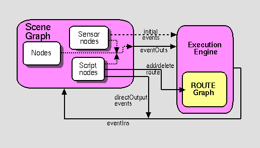
The task of defining the execution model for events is simplified by breaking it down into three subtasks:
The only nodes in the VRML 2.0 specification that can generate initial events are the sensor nodes, Collision group, and Script nodes. ExposedFields never generate initial events (they are always part of the event cascade) and neither do the interpolator nodes. So the first subtask, defining what causes an initial event, is satisfied by precisely defining the conditions under which each sensor or Script node will generate events. See Section 2.7, Scripting, for a discussion of when Script nodes generate initial events, and see the description for each sensor node for a discussion of when they generate initial events.
The second subtask, defining an ordering for initial events, is made easier by introducing the notion that all events are given time stamps. We can then guarantee determinism by requiring that an implementation produce results that are indistinguishable from an implementation that processes events in time stamp order, and defining an order for events that have the same time stamp (or declare that the results are inherently indeterministic and tell world creators, "Don't do that!"). Defining the execution model becomes manageable only if each change can be considered in isolation. Implementations may choose to process events out of order (or in parallel, or may choose not to process some events at all!) only if the results are the same as an implementation that completely processes each event as it occurs. VRML 2.0 is carefully designed so that implementations may reason about what effects a particular event might possibly have, allowing sophisticated implementations to be very efficient when processing events.
The third subtask, defining what happens during an event cascade, is made easier by not considering all possible route topologies at once. In particular, event cascades that contain loops and fan-ins are difficult to define and are considered separately (see -Sections 2.4.4, Loops, and 2.4.5, Fan-in and Fan-out).
Processing an event cascade ideally takes no time, which is why all events that are part of a given event cascade are given the same time stamp. ROUTE statements set up explicit dependencies between nodes, forcing implementations to process certain events in an event cascade before others.
For example, given nodes A, B, and C in the arrangement in Figure 2-7, where A is a TouchSensor detecting the user touching some geometry in the world, B is a Script that outputs TRUE and then FALSE every other time it receives input, and C is a TimeSensor that starts an animation, the ROUTE statements would be
        ROUTE A.touchTime TO B.toggleNow
        ROUTE A.touchTime TO C.set_startTime
        ROUTE B.toggle_changed TO C.set_enabled
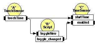
In this case, whether or not TimeSensor C will start generating events when TouchSensor A is touched depends on whether or not it is enabled, so an implementation must run Script B's script before deciding which events C should generate. If B outputs TRUE and C becomes active, then C should generate startTime_changed, enabled_changed, is-Active, fraction_changed, cycleTime, and time events. If B outputs FALSE and C becomes inactive, then it should only generate startTime_changed, enable_changed, and isActive events.
Paradoxical dependencies (when, for example, results of A depend on B and results of B depend on A) can be created, and implementations are free to do whatever they wish with them—results are undefined. See Section 2.4.5, Fan-in and Fan-out, for an explanation of what happens when more than one event is sent to a single eventIn.
Event cascades may contain loops, where an event E is routed to a node that generates an event that eventually results in E being generated again. To break such loops, implementations shall not generate two events from the same eventOut or to the same eventIn that have identical timestamps. This rule shall also be used to break loops created by cyclic dependencies between different sensor nodes.
In general, it is best to avoid route loops. There are some situations in which they're useful, however, and the loop-breaking rule combined with the dependencies implied by the routes are sufficient to make loops deterministic, except for some cases of cyclic dependencies (which are inherently indeterministic and must be avoided by world creators) and some cases of fan-in (which must also be avoided and are discussed later).
One simple situation in which a route loop might be useful is two exposedFields, A.foo and B.foo, with values that you want to remain identical. You can route them to each other, like this:
        ROUTE A.foo_changed TO B.set_foo
        ROUTE B.foo_changed TO A.set_foo
First, note that no events will be generated unless either A or B is changed. There must be either another route to A or B or a Script node that has access to and will change A or B, or neither A nor B will ever change. A route is a conduit for events; it does not establish equality between two fields. Or, in other words, if A.foo and B.foo start out with different values, then establishing a route between them will not make their values become equal. They will not become equal until either A receives a set_foo event or B receives a set_foo event. See Section 2.7, Scripting, for a description of how to write a script that generates initial events after the world has been loaded, if you want to guarantee equality between exposedFields.
The loop-breaking rule prevents an infinite sequence of events from being generated and results in "the right thing" happening. If A receives a set_foo event from somewhere, it sets its value and sends a set_foo event to B. B then sets its value and sends A another set_foo event, which A ignores since it has already received a set_foo event during this event cascade.
Fan-in occurs when two or more routes write to the same eventIn. If two events with different values but the same timestamp are received at an eventIn, the results are indeterminate.
Fan-out occurs when one eventOut routes to two or more eventIns. This results in sending any event generated by the eventOut to all of the eventIns.
Like loops, in general it is best to avoid fanning into a single eventIn, since it is possible to create situations that lead to undefined results. Fan-in can be useful if used properly, though. For example, you might create several different animations that can apply to a Transform node's translation field. If you know that only one animation will ever be active at the same time and all of the animations start with and leave the objects in the same position, then routing all of the animations to the set_translation eventIn is a safe and useful thing to do. However, if more than one animation might be active at the same time, results will be undefined and you will likely get different results in different browsers. In this case, you should insert a Script that combines the results of the animations in the appropriate way, perhaps by adding up the various translations and outputting their sum. The Script must have a different eventIn for each animation to avoid the problem of two events arriving at the same eventIn at the same time.
While designing VRML 2.0, various schemes for getting rid of ambiguous fan-in were considered. The simplest would be to declare all fan-in situations illegal, allowing only one route to any eventIn. That solution was rejected because it makes some simple things hard to do. Other possibilities that were considered and rejected included determining a deterministic ordering for each connection to an eventIn (rejected because determining an order is expensive and difficult) and built-in rules to automatically combine the values of each eventIn type, such as logical "OR" for SFBool events (rejected because it would make implementations more complex and because some event types [e.g., SFNode] don't have obvious combination rules). World creators are given the power to create ambiguous situations and are trusted with the responsibility to avoid such situations.
Fan-out is very useful and, by itself, can never cause undefined results. It can also be implemented very efficiently, because a node can't modify the events it receives. Only one event needs to be created for any eventOut, even if there are multiple routes leading from that eventOut.
The browser controls the passage of time in a world by causing TimeSensors to generate events as time passes. Specialized browsers or authoring applications may cause time to pass more quickly or slowly than in the real world, but typically the times generated by TimeSensors will roughly correspond to "real" time. A world's creator should make no assumptions about how often a TimeSensor will generate events but can safely assume that each time event generated will be greater than any previous time event.
The sampling of time is controlled by the VRML browser. This makes it much easier for the world creators, since they don't have to worry about synchronization of events, writing a "main loop," and so on. It also makes it much easier to create VRML authoring systems. If VRML had a model of time where independent applets each ran in a separate thread and made asynchronous changes to the world, then it would be very difficult for the user to "freeze time" and make necessary adjustments to the virtual world. Because time events all come from a single place— TimeSensor nodes—it is easy for a world creation system to control time during the authoring process.
Time (0.0) is equivalent to 00:00:00 GMT January 1, 1970. Absolute times are specified in SFTime or MFTime fields as double-precision floating point numbers. Negative absolute times are interpreted as happening before 1970.
Processing an event with timestamp t may only result in generating events with timestamps greater than or equal to t.
Defining an absolute origin for time isn't really necessary for proper functioning of VRML worlds. Absolute times are very rare in VRML files; they are almost always calculated during execution of the world relative to the occurrence of some event ("start this animation 2.3 seconds after the viewer walks into this room").
If you know where in the real world the VRML file will be viewed, then the absolute origin for time allows you to synchronize the real world and the virtual world. For example, if you know that your world will be viewed in California, then you can create a day-to-night animation that is driven by a TimeSensor and will match the sunrises and sunsets in California. VRML does not include a RealWorldPositionSensor that outputs the real-world position of the real-world VRML viewer, but if it did (perhaps when every computer includes a Global Positioning System satellite receiver, . . .) many very interesting applications merging the virtual and real worlds would become possible.
A frequently asked question is how can something be scheduled to start some amount of time "after the world is loaded." If time were defined to start "when the world is loaded," then this would be easy—the world creator would just give a TimeSensor an appropriate absolute startTime. One problem with this is defining precisely what is meant by "when the world is loaded." VRML browsers may load different parts of the world at different times or may preload parts of the world before they're actually needed. If the browser decides to preload part of the world because it knows that the user is traveling at a certain speed in a certain direction and will arrive there in 20 seconds, the world creator probably doesn't want a 5-second welcome animation to be performed before the user is anywhere near that part of the world. In this case, it is better for the world creator to use a ProximitySensor or a VisibilitySensor to generate an event that can then be used as the basis for starting animations, sounds, and so forth. Instead of thinking in terms of "when the world is loaded," it is better to think of "when the user enters my world" (ProximitySensor) or "when the user first sees . . ." (VisibilitySensor). Worlds created this way will be composable with other worlds, allowing the creation of the potentially infinite cyberspace of the future.
The rule that "events in the past cannot be generated" means that browsers are not responsible for simulating anything that occurred before the VRML file was loaded. The mental model is that a VRML file expresses the complete state of a virtual world at a given point in time. If the VRML browser knows exactly when the VRML file was written, then it could theoretically simulate all of the events that occurred between when the file was written and when it was read back into memory, just as if it had been simulating the world all along. However, VRML files do not record the time the world was written, and it is not always possible or convenient for the VRML browser to retrieve that information from the underlying operating system or transport mechanism. In addition, requiring the VRML browser to simulate the passage of an arbitrary amount of time after reading in every VRML file would be an unnecessary burden.
VRML does not distinguish between discrete events (such as those generated by a TouchSensor) and events that are the result of sampling a conceptually continuous set of changes (such as the fraction events generated by a TimeSensor). An ideal VRML implementation would generate an infinite number of samples for continuous changes, each of which would be processed infinitely quickly.
Before processing a discrete event, all continuous changes that are occurring at the discrete event's timestamp shall behave as if they generate events at that same timestamp.
This follows from the premise that an ideal implementation would be continuously generating events for continuous changes. A simple implementation can guarantee this by generating events for all active TimeSensors whenever a discrete event occurs. More sophisticated implementations can optimize this by noting dependencies and ensuring that if a node depends on both a discrete event and a continuous event, then it will always receive a continuous event along with the discrete event.
Beyond the requirements that continuous changes be up-to-date during the processing of discrete changes, the sampling frequency of continuous changes is implementation dependent. Typically a TimeSensor affecting a visible (or otherwise perceptible) portion of the world will generate events once per frame, where a frame is a single rendering of the world or one time-step in a simulation.
Thinking in terms of the ideal VRML implementation is a useful exercise and can resolve many situations that may at first seem ambiguous. It is impossible to implement the ideal, of course, but for well-behaved worlds the results of a well-implemented browser will be identical to the theoretical results of the ideal implementation. "Well behaved" means that the world creator didn't rely on any undefined behavior, such as assuming that TimeSensors would generate 30 events per second because that happened to be how quickly a particular browser could render their world on a particular type of machine.
In its quest to be machine- and implementation-neutral, the VRML specification tries to avoid any notion of rendering frames, pixels, or screen resolution. It is hoped that by avoiding such hardware-specific notions the VRML world description will be appropriate for many different rendering architectures, both present and future.
Authors often require that VRML worlds change dynamically in response to user inputs, external events, and the current state of the world. The proposition "if the vault is currently closed AND the correct combination is entered, open the vault" illustrates the type of problem which may need addressing. These kinds of decisions are expressed as Script nodes (see "3.40 Script") that receive events from other nodes, process them, and send events to other nodes. A Script node can also keep track of information between subsequent executions (i.e., retaining internal state over time).
This section describes the general mechanisms and semantics of all scripting language access protocols. Note that no particular scripting language is required by the VRML standard. Details for two scripting languages are in Appendix B, "Java Scripting Reference" and Appendix C, "JavaScript Scripting Reference", respectively. If either of these scripting languages are implemented, the Script node implementation shall conform with the definition described in the corresponding appendix.
Event processing is performed by a program or script contained in (or referenced by) the Script node's url field. This program or script may be written in any programming language that the browser supports.
The lack of a required scripting language for VRML is a problem for content creators who want their content to run on all VRML browsers. Unfortunately, the VRML community was unable to reach consensus on a language to require. The leading candidates were Java, JavaScript (or possibly a subset of JavaScript), and both Java and JavaScript. The scripting language situation isn't completely chaotic, however. Appendix C, Java Scripting Reference, and Appendix D, JavaScript Scripting Reference, define the language integration specifications if a browser chooses to implement one of these two.
A Script node is activated when it receives an event. The browser shall then execute the program in the Script node's url field (passing the program to an external interpreter if necessary). The program can perform a wide variety of actions including sending out events (and thereby changing the scene), performing calculations, and communicating with servers elsewhere on the Internet. A detailed description of the ordering of event processing is contained in "2.10 Event processing."
Script nodes may also be executed after they are created (see "2.12.3 Initialize() and shutdown()"). Some scripting languages may allow the creation of separate processes from scripts, resulting in continuous execution (see "2.12.6 Asynchronous scripts").
Script nodes receive events in timestamp order. Any events generated as a result of processing an event are given timestamps corresponding to the event that generated them. Conceptually, it takes no time for a Script node to receive and process an event, even though in practice it does take some amount of time to execute a Script.
Scripts are also activated when the file is loaded (see Section 2.12.3, Initialize and Shutdown). Some scripting languages allow the creation of asynchronous threads of execution, allowing scripts to be continuously active (see Section 2.7.6, Asynchronous Scripts). But it is expected that most scripts will act as "glue" logic along routes and will be executed only when they receive events.
Creating Script nodes that take a long time to process events (e.g., half a second) is a bad idea, since one slow Script node might slow down the entire VRML browser. At the very least, slow scripts will cause browsers problems as they try to deal with events with out-of-date time stamps, since even if the script takes three seconds to process an event, the events it generates will have time stamps equal to the original event.
If you want a Script node to perform some lengthy calculation, it is best to use a language like Java that allows the creation of separate threads, and perform the lengthy calculation in a separate thread. The user will then be able to continue interacting with the world while the calculation is proceeding.
The scripting language binding may define an initialize() method. This method shall be invoked before the browser presents the world to the user and before any events are processed by any nodes in the same VRML file as the Script node containing this script. Events generated by the initialize() method shall have timestamps less than any other events generated by the Script node. This allows script initialization tasks to be performed prior to the user interacting with the world.
Note that the specification is fuzzy about exactly when initialize() is called. The only requirement is that it be called before the Script generates any events (which can happen only after either an event has been received or initialize() is called). However, implementations should call the initialize() method as soon as possible after the Script node is created. For example, you might write a script that has an initialize() method that starts a thread that establishes and listens to a connection to a server somewhere on the network. Such a Script might not generate any events until it receives a message from the server, so an implementation that never called its initialize() method in the first place would, technically, be compliant with the requirements of the VRML specification.
Requiring that the initialize() method be called "as soon as possible" may not be desirable, either. Implementations may have prefetching strategies that call for loading part of the world into memory but not initializing it until the user performs some action (e.g., walks through the teleportation device). In this case, browser implementors are trusted to make reasonable decisions.
It is sometimes useful to create Scripts that have only an initialize() method. This technique can be used to ensure that exposedFields along an event cascade route start out with reasonable values. The Script simply generates an initial event (with a value that might be specified as a field of the Script, for example) in its initialize() method. The same technique is also useful for generating geometry or textures at load time; transmitting code that generates nodes rather than specifying the nodes explicitly, can save lots of bandwidth.
If a Script has no eventIns and doesn't start up an asynchronous thread, then it can safely be deleted as soon as its initialize() method has been called. There is no way for such a Script to ever generate events after the initialize() method is finished.
Likewise, the scripting language binding may define a shutdown() method. This method shall be invoked when the corresponding Script node is deleted or the world containing the Script node is unloaded or replaced by another world. This method may be used as a clean-up operation, such as informing external mechanisms to remove temporary files. No other methods of the script may be invoked after the shutdown() method has completed, though the shutdown() method may invoke methods or send events while shutting down. Events generated by the shutdown() method that are routed to nodes that are being deleted by the same action that caused the shutdown() method to execute will not be delivered. The deletion of the Script node containing the shutdown() method is not complete until the execution of its shutdown() method is complete.
Again, the specification doesn't precisely specify when shutdown() is called. Unless you are writing a script that starts separate threads, you probably won't need a shutdown() method.
The scripting language binding may define an eventsProcessed() method that is called after one or more events are received. This method allows Scripts that do not rely on the order of events received to generate fewer events than an equivalent Script that generates events whenever events are received. If it is used in some other time-dependent way, eventsProcessed() may be nondeterministic, since different browser implementations may call eventsProcessed() at different times.
For a single event cascade, a given Script node's eventsProcessed() method shall be called at most once. Events generated from an eventsProcessed() method are given the timestamp of the last event processed.
Sophisticated implementations may determine that they can defer executing certain scripts, resulting in several events being sent to a script at once. The eventsProcessed() routine is an optimization that lets the script creator be more efficient in these cases. For example, if you create a simple Script that receives set_a and set_b events and generates sum_changed events where sum = a + b, it is more efficient to calculate the sum and generate the sum_changed event in an eventsProcessed() routine, after all set_a and set_b events have been received. The end result is the same as generating sum_changed events whenever a set_a or set_b event is received, but fewer events will be generated.
Of course, if it is important that events for all of the changes to sum are generated, eventsProcessed() should not be used. For example, you might create a script that recorded the time and value of each event it receives, which could be used to generate a history of the sum over time. Most of the time, however, only the most current result is of interest.
Scripts that have access to other nodes (via SFNode/MFNode fields or eventIns) and that have their directOutput field set to TRUE may directly post eventIns to those nodes. They may also read the last value sent from any of the node's eventOuts.
When setting a value in another node, implementations are free to either immediately set the value or to defer setting the value until the Script is finished. When getting a value from another node, the value returned shall be up-to-date; that is, it shall be the value immediately before the time of the current timestamp (the current timestamp returned is the timestamp of the event that caused the Script node to execute).
Script nodes that are not connected by ROUTE statements may be executed asynchronously. If multiple directOutput Scripts read from and/or write to the same node, the results may be undefined.
The directOutput field is a hint to the browser that the Script may directly read or write other nodes in the scene, instead of just receiving and sending events through its own eventIns and eventOuts. When directOutput is FALSE (the default), several optimizations are possible that cannot be safely performed if the Script might directly modify other nodes in the scene. If we assumed that browsers could examine the Script's code and look at the calls it makes before execution, then this hint wouldn't be necessary. However, it is assumed that scripts are black boxes and browsers may not be able to examine their code. For example, Java byte code may be passed directly to a Java interpreter embedded in the computer's operating system, separate from the VRML browser.
If a Script node, with its directOutput set to FALSE, directly modifies other nodes, results are undefined. Browsers are not required to check for this case because it would slow down scripts that have set the field correctly (slowing down execution of the common case to test for a rare error condition would violate the design principle that VRML should be high performance). Errors due to incorrectly setting the directOutput flag are likely to be hard to find, since they will cause some browsers to make invalid assumptions about what optimizations they can perform and have no effect on other browsers that perform different optimizations.
Scripts that have their directOutput field set to TRUE can only read or write nodes to which they have access. There are four ways for scripts to get access to other nodes:
Since browsers know whether or not a script might directly modify other nodes (from the directOutput field), and because browsers know which nodes scripts may access (from their fields, events received, etc.), they can determine which parts of the scene cannot possibly change. And, knowing that, browsers may decide to perform certain optimizations that are only worthwhile if the scene doesn't change. For example, a browser could decide to create texture map "imposters"—images of the object from a particular point of view that can be drawn less expensively than the object itself—for objects that cannot change. It is best to limit the number of nodes to which a script has access so that browsers have maximum opportunity for such optimizations.
Often the same task can be performed either using a ROUTE or by giving a script direct access to a node and setting its directOutput field to TRUE. In general, it is better to use a ROUTE, since the ROUTE gives the browser more information about what the script is doing and, therefore, gives the browser more potential optimizations.
Some languages supported by VRML browsers may allow Script nodes to spontaneously generate events, allowing users to create Script nodes that function like new Sensor nodes. In these cases, the Script is generating the initial events that causes the event cascade, and the scripting language and/or the browser shall determine an appropriate timestamp for that initial event. Such events are then sorted into the event stream and processed like any other event, following all of the same rules including those for looping.
Java, for example, allows the creation of separate threads. Those threads can generate eventOuts at any time, essentially allowing the Script containing the Java code to function as a new, user-defined sensor node.
If you want to create scalable worlds, you should be careful when creating asynchronous threads. You can easily swamp any CPU by creating a lot of little scripts that are all constantly busy. Make each script as efficient as possible, and make each thread inactive (blocked and waiting for input from the network, for example) as much of the time as possible.
The Script node's url field may specify a URL which refers to a file (e.g., using protocol http:) or incorporates scripting language code directly in-line (e.g., using protocol javabc:). The MIME-type of the returned data defines the language type. Additionally, instructions can be included in-line using either the data: protocol (which allows a MIME-type specification) or a "2.5.5 Scripting Language Protocol" defined for the specific language (from which the language type is inferred).
For example, the following Script node has one eventIn field named start and three different URL values specified in the url field: Java, JavaScript, and inline JavaScript:
    Script {
      eventIn SFBool start
      url [ "http://foo.com/fooBar.class",
        "http://foo.com/fooBar.js",
        "javascript:function start(value, timestamp)
          { ... }"
      ]
    }
In the above example when a start eventIn is received by the Script node, one of the scripts found in the url field is executed. The Java code is the first choice, the JavaScript code is the second choice, and the inline JavaScript code the third choice. A description of order of preference for multiple valued URL fields may be found in "2.5.2 URLs."
An earlier design of the Script node had a languageType SFString field and a script SFString field that either contained or pointed to the script code. Using the same URL paradigm for the script code as is used for other media types that aren't part of VRML (images, movies, sounds) is a much better design and had several unexpected benefits:
Events received by the Script node are passed to the appropriate scripting language method in the script. The method's name depends on the language type used. In some cases, it is identical to the name of the eventIn; in others, it is a general callback method for all eventIns (see the scripting language appendices for details). The method is passed two arguments: the event value and the event timestamp.
Passing the event time stamp along with every event makes it easy for script authors to generate results that are consistent with VRML's ideal execution model. If time stamps were not easily available, then script authors that wished to schedule things relative to events (e.g., start animations or sounds two seconds after receiving an event) would be forced to schedule them relative to the time the script happened to be executed. That wouldn't be a problem for an ideal implementation that processed all events the instant they happened, but it could cause synchronization problems for real implementations, since two scripts triggered by the same event will be executed at slightly different times (ignoring multiprocessor implementations, which are possible and could execute scripts in parallel).
There is no way for a Script node to find out what nodes are sending it events, and no way for it to find out what nodes are receiving the events it generates (unless it is a directOutput Script that is directly sending events to nodes, of course). This was done to restrict the number of nodes to which a script potentially has access, allowing browsers more opportunities for optimization (refer back to Section 2.7.5, Scripts with Direct Outputs). Passing some sort of opaque node identifier with each event was also considered, and would have allowed scripts to do some interesting things with events that were fanned-in from several different nodes. However, that feature probably would not be used often enough to justify the cost of passing an extra parameter with every event.
The fields, eventIns, and eventOuts of a Script node are accessible from scripting language methods. Events can be routed to eventIns of Script nodes and the eventOuts of Script nodes can be routed to eventIns of other nodes. Another Script node with access to this node can access the eventIns and eventOuts just like any other node (see "2.12.5 Scripts with direct outputs").
It is recommended that user-defined field or event names defined in Script nodes follow the naming conventions described in "2.7 Fields, eventIns, and eventOuts semantics."
Fields defined in the Script node are available to the script through a language-specific mechanism (e.g., a variable is automatically defined for each field and event of the Script node). The field values can be read or written and are persistent across method calls. EventOuts defined in the Script node may also be read; the returned value is the last value sent to that eventOut.
The script can access any eventIn or eventOut of any node to which it has access. The syntax of this mechanism is language dependent. The following example illustrates how a Script node accesses and modifies an exposed field of another node (i.e., sends a set_translation eventIn to the Transform node) using JavaScript:
    DEF SomeNode Transform { }
    Script {
      field   SFNode  tnode USE SomeNode
      eventIn SFVec3f pos
      directOutput TRUE
      url "javascript:
        function pos(value, timestamp) {
          tnode.set_translation = value;
        }"
    }
The language-dependent mechanism for accessing eventIns or eventOuts (or the eventIn or eventOut part of an exposedField) shall support accessing them without their "set_" or "_changed" prefix or suffix, to match the ROUTE statement semantics. When accessing an eventIn named "zzz" and an eventIn of that name is not found, the browser shall try to access the eventIn named "set_zzz". Similarly, if accessing an eventOut named "zzz" and an eventOut of that name is not found, the browser shall try to access the eventIn named "zzz_changed".
If the Script accesses the eventIns or eventOuts of other nodes, then it must have its directOutput field set to TRUE, as previously described in Section 2.7.5, Scripts with Direct Outputs.
EventIns of other nodes are write-only; the only operation a directOutput Script may perform on such eventIns is sending them an event. Note that this is exactly the opposite of the Script node's own eventIns, which are read-only—the Script can just read the value and time stamp for events it receives.
EventOuts of other nodes are read-only; the only operation a directOutput Script may perform on them is reading the last value they generated (see Chapter 4, Fields and Events, for the definition of the initial value of eventOuts before they have generated any events). A Script's own eventOuts, on the other hand, can be both read and written by the script.
Fields of other nodes are completely opaque and private to the node. A Script may read and write its own fields as it pleases, of course. If fields were not private to the nodes that owned them it would be quite difficult to write a robust Script node, since other nodes could possibly change the Script's fields at any time.
ExposedFields of other nodes are just an eventIn, an eventOut, and a field. The eventIn may be written to by a directOutput Script, and the eventOut may be read, giving complete read/write access to the field.
Each scripting language provides a mechanism for allowing scripts to send a value through an eventOut defined by the Script node. For example, one scripting language may define an explicit method for sending each eventOut, while another language may use assignment statements to automatically defined eventOut variables to implicitly send the eventOut. Sending multiple values through an eventOut during a single script execution will result in the "last" event being sent, where "last" is determined by the semantics of the scripting language being used.
The specification should be more precise here. To avoid potential problems, you should not write scripts that generate events from the same eventOut that have the same time stamp. And browser implementors should create Script node implementations that send out only the "last" eventOut with a given time stamp, assuming that the scripting language being used has a well-defined execution order (which may not be true if languages that support implicit parallelism are ever used with VRML).
The browser interface provides a mechanism for scripts contained by Script nodes to get and set browser state (e.g., the URL of the current world). This section describes the semantics of methods that the browser interface supports. An arbitrary syntax is used to define the type of parameters and returned values. The specific appendix for a language contains the actual syntax required. In this abstract syntax, types are given as VRML field types. Mapping of these types into those of the underlying language (as well as any type conversion needed) is described in the appropriate language appendix.
The getName() and getVersion() methods return a string representing the "name" and "version" of the browser currently in use. These values are defined by the browser writer, and identify the browser in some (unspecified) way. They are not guaranteed to be unique or to adhere to any particular format and are for information only. If the information is unavailable these methods return empty strings.
The getCurrentSpeed() method returns the average navigation speed for the currently bound NavigationInfo node in meters per second, in the coordinate system of the currently bound Viewpoint node. If speed of motion is not meaningful in the current navigation type, or if the speed cannot be determined for some other reason, 0.0 is returned.
The getCurrentFrameRate() method returns the current frame rate in frames per second. The way in which frame rate is measured and whether or not it is supported at all is browser dependent. If frame rate measurement is not supported or cannot be determined, 0.0 is returned.
The getWorldURL() method returns the URL for the root of the currently loaded world.
The replaceWorld() method replaces the current world with the world represented by the passed nodes. An invocation of this method will usually not return since the world containing the running script is being replaced. Scripts that may call this method shall have mustEvaluate set to TRUE.
The loadURL() method loads the first recognized URL from the specified url field with the passed parameters. The parameter and url arguments are treated identically to the Anchor node's parameter and url fields (see "3.2 Anchor"). This method returns immediately. However, if the URL is loaded into this browser window (e.g., there is no TARGET parameter to redirect it to another frame), the current world will be terminated and replaced with the data from the specified URL at some time in the future. Scripts that may call this method shall set mustEvaluate to TRUE.
The setDescription() method sets the passed string as the current description. This message is displayed in a browser dependent manner. An empty string clears the current description. Scripts that may call this method must have mustEvaluate set to TRUE.
The createVrmlFromString() method imports a string consisting of a VRML scene description, parses the nodes contained therein, and returns the root nodes of the corresponding VRML scene. The string must be self-contained (i.e., USE statements inside the string may refer only to nodes DEF'ed in the string, and non-built-in node types used by the string must be prototyped using EXTERNPROTO or PROTO statements inside the string).
The createVrmlFromURL() instructs the browser to load a VRML scene description from the given URL or URLs. The VRML file referred to must be self-contained (i.e., USE statements inside the string may refer only to nodes DEF'ed in the string, and non-built-in node types used by the string must be prototyped using EXTERNPROTO or PROTO statements inside the string). After the scene is loaded, event is sent to the passed node returning the root nodes of the corresponding VRML scene. The event parameter contains a string naming an MFNode eventIn on the passed node.
These methods respectively add and delete a route between the given event names for the given nodes. Scripts that may call this method must have directOutput set to TRUE.
The composability and scalability design goals put severe restrictions on the Script node browser interface API. For example, a call that returned the root nodes of the world was considered and rejected because it would allow a script unrestricted access to almost all of the nodes in the world, severely limiting a browser's ability to reason about what might and might not be changing. Many features that were initially part of the API were moved into nodes in the scene, because doing so made the design much more composable and consistent.
The functions that are left are very general and quite powerful. Several of the standard nodes in the VRML specification could be implemented via prototypes that used these API calls. For example, the Anchor node could be implemented as a Group, a TouchSensor, and a Script that made loadURL() and setDescription() calls at the appropriate times, and an Inline could be implemented as a Group and a Script that called createVrmlFromURL(url, group, "set_children") in its initialize() method.
Conceptually speaking, every VRML world contains a viewpoint from which the world is currently being viewed. Navigation is the action taken by the user to change the position and/or orientation of this viewpoint thereby changing the user's view. This allows the user to move through a world or examine an object. The NavigationInfo node (see "3.29 NavigationInfo") specifies the characteristics of the desired navigation behaviour, but the exact user interface is browser-dependent. The Viewpoint node (see "3.53 Viewpoint") specifies key locations and orientations in the world that the user may be moved to via scripts or browser-specific user interfaces.
The browser may allow the user to modify the location and orientation of the viewer in the virtual world using a navigation paradigm. Many different navigation paradigms are possible, depending on the nature of the virtual world and the task the user wishes to perform. For instance, a walking paradigm would be appropriate in an architectural walkthrough application, while a flying paradigm might be better in an application exploring interstellar space. Examination is another common use for VRML, where the world is considered to be a single object which the user wishes to view from many angles and distances.
The NavigationInfo node has a type field that specifies the browser the navigation paradigm for this world. The actual user interface provided to accomplish this navigation is browser-dependent. See "3.29 NavigationInfo" for details.
The browser controls the location and orientation of the viewer in the world, based on input from the user (using the browser-provided navigation paradigm) and the motion of the currently bound Viewpoint node (and its coordinate system). The VRML author may place any number of viewpoints in the world at important places from which the user might wish to view the world. Each viewpoint is described by a Viewpoint node. Viewpoints exist in their parent's coordinate system, and both the viewpoint and the coordinate system may be changed to affect the view of the world presented by the browser. Only one viewpoint may be bound at a time. A detailed description of how the Viewpoint node operates may be found in "2.6.10 Bindable children nodes" and "3.53 Viewpoint."
User navigation is independent of the location and orientation of the currently bound Viewpoint node; navigation is performed relative to the Viewpoint's location and does not affect the values of a Viewpoint node. The location of the viewer may be determined with a ProximitySensor node (see "3.38 ProximitySensor").
Viewpoints are a powerful feature for improving usability of your worlds. You can create guided tours by binding the user to a viewpoint and then animating the viewpoint along a predefined path (automatic navigation through the virtual world). Keep in mind that many users will have difficulty navigating through 3D spaces; combining viewports with the other interaction features in VRML creates "point-and-click" worlds that are very easy to navigate.
A VRML file may contain Collision nodes (see "3.8 Collision") and NavigationInfo nodes that may influence the browser's navigation paradigm. The browser is responsible for detecting collisions between the viewer and the objects in the virtual world, and is also responsible for adjusting the viewer's location when a collision occurs. Browsers shall not disable collision detection except for the special cases listed below. Collision nodes may be used to generate events when the viewer collides with objects, and may be used to designate that certain objects should be treated as transparent to collisions. Support for inter-object collision is not specified. The NavigationInfo types of WALK, FLY, and NONE shall strictly support collision detection. However, the NavigationInfo types ANY and EXAMINE may temporarily disable collision detection during navigation, but shall not disable collision detection during the normal execution of the world. See "3.29 NavigationInfo" for details on the various navigation types.
NavigationInfo nodes may be used to specify certain parameters often used by browser navigation paradigms. The size and shape of the viewer's avatar determines how close the avatar may be to an object before a collision is considered to take place. These parameters may also be used to implement terrain following by keeping the avatar a certain distance above the ground. They may additionally be used to determine how short an object must be for the viewer to automatically step up onto it instead of colliding with it.
The VRML lighting model provides detailed equations which define the colours to apply to each geometric object. For each object, the values of the Material node, Color node and texture currently being applied to the object are combined with the lights illuminating the object and the currently bound Fog node. These equations are designed to simulate the physical properties of light striking a surface.
A Shape node is unlit if either of the following is true:
Note the special cases of geometry nodes that do not support lighting (see "3.24 IndexedLineSet" and "3.36 PointSet" for details).
A shape will be lit if you specify a material to be used for lighting. Shapes are unlit and bright white by default; you will almost always specify either colors (using a Color node) or a material (using a Material node). No lighting was chosen as the default because it is faster than lighting (wherever possible in VRML, default values were chosen to give maximum performance), and bright white was chosen so objects show up against the default black background.
If the shape is unlit, the colour (Irgb) and alpha (A, 1-transparency) of the shape at each point on the shape's geometry is given in Table 2-5.
| Texture type | Colour per-vertex or per-face |
Colour NULL |
| No texture | Irgb=
ICrgb A = 1 |
Irgb=
(1, 1, 1) A = 1 |
| Intensity (one-component) |
Irgb=
IT × ICrgb A = 1 |
Irgb
= (IT,IT,IT
) A = 1 |
| Intensity+Alpha (two-component) |
Irgb=
I T × ICrgb A = AT |
Irgb=
(IT,IT,IT
) A = AT |
| RGB (three-component) |
Irgb=
ITrgb A = 1 |
Irgb=
ITrgb A = 1 |
| RGBA (four-component) |
Irgb=
ITrgb A = AT |
Irgb=
ITrgb A = AT |
where:
AT = normalized [0, 1] alpha value from 2 or 4
component texture image
ICrgb = interpolated
per-vertex colour, or per-face colour, from Color node
IT = normalized [0, 1] intensity from 1 or 2
component texture image
ITrgb= colour from
3-4 component texture image
If a full-color texture is given, it defines the colors on unlit geometry (if per-vertex or per-face colors are also given, they are ignored). If an intensity map (one- or two-component texture) is given, then it is either used as a gray-scale texture or, if colors are also specified, it is used to modulate the colors. If there is no texture, then either the per-vertex or per-face colors are used, if given, or white is used. Alpha values are always either 1.0 (fully opaque) or come from the texture image, if the texture image contains transparency.
If colors are specified per vertex, then they should be interpolated across each polygon (polygon and face mean the same thing--a series of vertices that lie in the same plane and define a closed 2D region). The method of interpolation is not defined. Current rendering libraries typically triangulate polygons with more than three vertices and interpolate in RGB space, but neither is required. Pretriangulate your shapes and limit the color differences across any given triangle (by splitting triangles into smaller triangles, if necessary) if you want to guarantee similar results in different implementations. Also note that some implementations may not support per-vertex coloring at all and may approximate it by averaging the vertex colors to produce one color per polygon.
Allowing the specification of transparency values per face or per vertex was considered. While that would have made the Color node more consistent with the Material and texture nodes (which allow both colors and transparencies to be specified), it would have added complexity to an already complex part of the specification for a feature that would be rarely used.
If the shape is lit (i.e., a Material and an Appearance node are specified for the Shape), the Color and Texture nodes determine the diffuse colour for the lighting equation as specified in Table 2-6.
Texture type |
Colour per-vertex or per-face |
Color node NULL |
| No texture | ODrgb = ICrgb A = 1-TM |
ODrgb = IDrgb A = 1-TM |
| Intensity texture (one-component) |
ODrgb = IT
× ICrgb A = 1-TM |
ODrgb = IT
× IDrgb A = 1-TM |
| Intensity+Alpha texture (two-component) |
ODrgb = IT
× ICrgb A = AT |
ODrgb = IT
× IDrgb A = AT |
| RGB texture (three-component) |
ODrgb = ITrgb A = 1-TM |
ODrgb = ITrgb A = 1-TM |
| RGBA texture (four-component) |
ODrgb = ITrgb A = AT |
ODrgb = ITrgb A = AT |
where:
IDrgb =
material diffuseColor
ODrgb = diffuse
factor, used in lighting equations below
TM = material transparency
... and all other terms are as above.
The rules (expressed in Table 2-4) for combining texture, Color, and Material nodes are as follows:
Textures have the highest priority; texture colors will be used if a full-color texture is specified (and the colors in the Color node or diffuseColor of the Material node will be ignored). If an intensity texture is specified, it will be used to modulate the diffuse colors from either the Color or Material nodes. If the texture contains transparency information, it is always used instead of the Material's transparency field.
Per-vertex or per-face colors specified in a Color node have the next highest priority and override the Material node's diffuseColor field unless a full-color texture is being used.
The diffuseColor specified in the Material node has lowest priority and will be used only if there is no full-color texture or Color node. The texture and Color nodes affect only the diffuseColor of the Material; the other Material parameters (specularColor, emissiveColor, etc.) are always used as is.
An ideal VRML implementation will evaluate the following lighting equation at each point on a lit surface. RGB intensities at each point on a geometry (Irgb) are given by:
Irgb = IFrgb
× (1 -f0) + f0 × (OErgb + SUM( oni × attenuationi ×
spoti × ILrgb
×
(ambienti + diffusei + specular i)))
where:
attenuationi = 1 / max(c1 + c2 × dL + c3 × dL²
, 1 )
ambienti = Iia × ODrgb × Oa
diffusei = Ii × ODrgb × ( N · L )
specular i = Ii × OSrgb × ( N · ((L + V)
/ |L + V|))shininess × 128
and:
|
|
|---|---|
| lighti is PointLight or DirectionalLight | 1 |
| spotAngle >= spotCO | 0 |
| spotAngle <= spotBW | 1 |
| spotBW < spotAngle < spot CO | (spotAngle - spotCO ) / (spotBW-spotCO) |
| Condition | f0 = |
|---|---|
| no fog | 1 |
| fogType "LINEAR", dV < fogVisibility | (fogVisibility-dV) / fogVisibility |
| fogType "LINEAR", dV > fogVisibility | 0 |
| fogType "EXPONENTIAL", dV < fogVisibility | exp(-dV / (fogVisibility-dV ) ) |
| fogType "EXPONENTIAL", dV > fogVisibility | 0 |
The following design note is useful to both authors and implementors.
These lighting equations are intended to make it easier for implementors to match the ideal VRML lighting model to the lighting equations used by their rendering library. However, understanding the lighting equations and understanding the approximations commonly made to map them to common rendering libraries can help you create content that looks good on all implementations of VRML.
Performing the lighting computation per pixel (Phong shading) is not feasible on current graphics software and hardware; the hardware and software just aren't fast enough. However, within the next couple of years per-pixel lighting will probably be a common feature of very high-performance graphics hardware, and it may be a common feature in inexpensive software and hardware in five years, so VRML specifies an ideal lighting model that can grow with hardware progress. Because 3D graphics technology is evolving so fast, it is better to anticipate future developments and allow current implementations to approximate an ideal specification, rather than choosing a least-common-denominator model that will limit future implementations.
Current implementations typically perform lighting calculations only for each vertex of each polygon. The resulting colors are then linearly interpolated across the polygon (Gouraud shading). The most noticeable effects of this approximation are fuzzy or inaccurate edges for specular highlights, spotlights, and point lights, since the tessellation of the geometry affects where lighting calculations are done. The approximation can be improved by subdividing the polygons of the geometry, creating more vertices (and therefore forcing implementations to do more lighting calculations). This will, of course, decrease performance.
Application of a texture map should ideally occur before lighting, replacing the diffuse term of the lighting equation at each pixel. However, since lighting computations are done per vertex and not per pixel, texture maps are combined with the interpolated color. That is, instead of performing the ideal lighting calculation
OErgb + SUM(oni × attenuationi × spoti ×Lrgb
× (ambient i + (Ii × ODrgb× ( N · L )) + speculari) )
this approximation is computed when texturing
ITrgb × (OErgb + SUM(oni × attenuationi × spoti × ILrgb
× (Iia × Oa + Ii × ( N · L ) + speculari) ) )
The terms inside the parentheses are computed per vertex and interpolated across the polygon, and a color is computed from the texture map and multiplied per pixel. Note that the approximation equals the ideal equation for purely diffuse objects (objects where OErgb = speculari = 0.0), and since the diffuse term dominates for most objects, the approximation will closely match the ideal for most textured objects. Errors are caused by the texture affecting the specular and emissive colors of the object.
Finally, implementations will be forced to quantize the ideal 0.0 to 1.0 RGB colors of the VRML specification into the number of colors supported by your graphics hardware. This is becoming less of an issue each year as more and more hardware supports millions of colors (24 bits of color--16 million colors--is near the limit of human perception), but displayed colors can vary widely on displays that support only thousands or hundreds of colors. In addition, different computer monitors can display the same colors quite differently, resulting in different-looking worlds. The VRML file format does not attempt to address any of these issues; it is meant to be only an ideal description of a virtual world.
The VRML lighting equations are based on the simple illumination equations given in [FOLE] and [OPEN].
![]()