Copyright © 1997 by Rikk Carey and Gavin Bell
This chapter provides a detailed definition of the syntax and semantics of each node in the VRML specification. The nodes are listed in alphabetical order.
This chapter provides a detailed definition of the syntax and semantics of each node in VRML. Table 3-1 lists the topics in this chapter.
In this chapter, the first item in each section is the public interface specification for the node. This interface defines the names and types of the fields and events for the node, as well as the default values for the fields of the node. Note that this syntax is not the actual file format syntax. However, the parts of the interface that are identical to the file syntax are in bold. For example, the following defines the Collision node's public interface and file format:
Collision {
eventIn MFNode addChildren
eventIn MFNode removeChildren
exposedField MFNode children []
exposedField SFBool collide TRUE
field SFVec3f bboxCenter 0 0 0 # (- ,)
field SFVec3f bboxSize -1 -1 -1 # (0,) or -1,-1,-1
field SFNode proxy NULL
eventOut SFTime collideTime
}
,)
field SFVec3f bboxSize -1 -1 -1 # (0,) or -1,-1,-1
field SFNode proxy NULL
eventOut SFTime collideTime
}
Note that the interface specification also includes the value ranges
for the node's fields and exposedFields (where appropriate).
Parentheses imply that the range bound is exclusive, while brackets
imply that the range value is inclusive. For example, a range of (-![]() ,1] defines the lower bound as -
,1] defines the lower bound as -![]() exclusively and the upper bound as 1
inclusively.
exclusively and the upper bound as 1
inclusively.
The fields and events contained within the public interface of node types are ordered as follows:
![]()
Anchor {
eventIn MFNode addChildren
eventIn MFNode removeChildren
exposedField MFNode children []
exposedField SFString description ""
exposedField MFString parameter []
exposedField MFString url []
field SFVec3f bboxCenter 0 0 0 # (-,)
field SFVec3f bboxSize -1 -1 -1 # (0,) or -1,-1,-1
}
The Anchor grouping node retrieves the content of a URL when the user activates (e.g., clicks) some geometry contained within the Anchor node's children. If the URL points to a valid VRML file, that world replaces the world of which the Anchor node is a part (except when the parameter field, described below, alters this behaviour). If non-VRML data is retrieved, the browser shall determine how to handle that data; typically, it will be passed to an appropriate non-VRML browser.
The name Anchor comes from the HTML Anchor tag (<A HREF=...>), which is used to create hyperlinked text in HTML. It was called WWWAnchor in VRML 1.0, but the WWW was dropped.
Exactly how a user activates geometry contained by the Anchor node depends on the pointing device and is determined by the VRML browser. Typically, clicking with the pointing device will result in the new scene replacing the current scene. An Anchor node with an empty url does nothing when its children are chosen. A description of how multiple Anchors and pointing-device sensors are resolved on activation is contained in "2.6.7 Sensor nodes."
A description of children, addChildren, and removeChildren fields and eventIns may be found in "2.6.5 Grouping and children nodes."
The description field in the Anchor node specifies a textual description of the Anchor node. This may be used by browser-specific user interfaces that wish to present users with more detailed information about the Anchor.
The candidate Anchor is the Anchor with geometry that is underneath the pointing device. The pointing device is usually a mouse (or a mouse substitute like a trackball or touchpad).
The parameter exposed field may be used to supply any additional information to be interpreted by the VRML or HTML browser. Each string shall consist of "keyword=value" pairs. For example, some browsers allow the specification of a 'target' for a link to display a link in another part of the HTML document. The parameter field is then:
Anchor {
parameter [ "target=name_of_frame" ]
...
}
The parameter field was added to allow Anchors to bring up hyperlinks in other HTML frames on the same Web page. When VRML 2.0 was originally being designed, Netscape Navigator was the only HTML browser that supported multiple frames, so instead of adding a frame or target field just to support that feature, the more general parameter field was added to Anchor. That avoided adding any Netscape-specific features to VRML and allows for future additions.
An Anchor node may be used to bind the initial Viewpoint node in a world by specifying a URL ending with "#ViewpointName" where "ViewpointName" is the name of a viewpoint defined in the file. For example:
Anchor {
url "http://www.school.edu/vrml/someScene.wrl#OverView"
children Shape { geometry Box {} }
}
specifies an anchor that loads the file "someScene.wrl" and binds the initial user view to the Viewpoint node named "OverView" when the Anchor node's geometry (Box) is activated. If the named Viewpoint node is not found in the file, the file is loaded using the default Viewpoint node binding stack rules (see "3.53 Viewpoint").
If the url field only contains a "#ViewpointName" (i.e. no file name), the Viewpoint node named "ViewpointName" in the current world shall be bound (set_bind TRUE). See "3.53 Viewpoint" for the Viewpoint transition rules that specify how browsers shall interpret the transition from the old Viewpoint node to the new one. For example:
Anchor {
url "#Doorway"
children Shape { geometry Sphere {} }
}
binds the viewer to the viewpoint defined by the "Doorway" viewpoint in the current world when the sphere is activated. In this case, if the Viewpoint is not found, nothing is done on activation.
More details on the url field are contained in "2.5 VRML and the World Wide Web."
Since navigating around 3D worlds can be difficult, it is recommended that authors provide navigation assists whenever possible. The Anchor node serves as an excellent tool for creating simple guided tours or navigation aids in a 3D world. Place signposts or other recognizable objects (e.g., labeled buttons) throughout the world with Anchor nodes as parents, and define each Anchor to refer to a Viewpoint defined in the world (e.g., Anchor { url "#someViewpoint" ... }). Typically, there should be at least one visible signpost from every Viewpoint. This ensures that the user knows where to go after visiting each stop. When creating guided tours, authors should include backward and forward links at each signpost. Remember that VRML does not specify what happens during the transition to a Viewpoint and thus could perform a jump cut, an animated movement, or some other transitional effect. If an author wishes to control the transition precisely, then the only option is to use TouchSensors with Scripts programmed to bind and unbind Viewpoints, which are animated by PositionInterpolators and OrientationInterpolators. This is a much more complicated task than using the simple Anchor node.
The bboxCenter and bboxSize fields specify a bounding box that encloses the Anchor's children. This is a hint that may be used for optimization purposes. If the specified bounding box is smaller than the actual bounding box of the children at any time, the results are undefined. The default bboxSize value, (-1, -1, -1), implies that the bounding box is not specified and if needed must be calculated by the browser. A description of bboxCenter and bboxSize fields may be found in "2.6.4 Bounding boxes."
Anchor is equivalent to a prototype containing a couple of Group nodes, a Touch-Sensor, and a Script. It is a standard node partly because it makes it easier to convert VRML 1.0 files (which use WWWAnchor) to VRML 2.0, and partly because it is convenient to have simple hyperlinking support prepackaged in a convenient form.
There are many hyperlinking tasks for which Anchor is inadequate. For example, if you want a hyperlink to occur after the user has accomplished some task, then you must use a Script node that calls loadURL(). If you want to load several different pieces of information into several other frames you will also have to use a Script that makes several calls to loadURL(). The basic building blocks of Scripts and sensors allow you to do almost anything; the Anchor node is only meant to address the most basic hyperlinking tasks.
The following example illustrates typical use of the Anchor node. The first Anchor links the Box geometry to another VRML world that replaces this one after the Anchor is activated. The second Anchor links the Sphere to a Viewpoint in this world. When the user clicks on the Sphere, the browser's view is transported to the Viewpoint. The third Anchor links a Cone to a frame on an HTML page. When the user clicks on the Cone, the frame is activated:
#VRML V2.0 utf8
Group { children [
Transform {
translation -5 0 0
children Anchor {
url "http://www.barbie.web/~barbie/dollhouse.wrl"
description "Link to Barbie's Home Page pad"
children Shape {
geometry Box {}
appearance DEF A1 Appearance {
material Material {
diffuseColor 1 1 1
ambientIntensity 0.33
specularColor 1 1 1
shininess 0.5
}
}
}
}
}
Transform {
children Anchor {
url "#NiceView"
description "Link to a nice view in this scene"
children Shape { geometry Sphere {} appearance USE A1 }
}
}
Transform {
translation 5 0 0
children Anchor {
url "http://www.barbie.web/~barbie/index.html"
description "Link to frame in Barbie's home page"
parameter "target=name_of_frame"
children Shape {
geometry Cone {}
appearance USE A1 }
}
}
DEF NiceView Viewpoint {
position 0 0 -20
description "A Nice View"
}
]}
![]()
Appearance {
exposedField SFNode material NULL
exposedField SFNode texture NULL
exposedField SFNode textureTransform NULL
}
The Appearance node specifies the visual properties of geometry by defining the Material and texture nodes. The value for each of the fields in this node can be NULL. However, if the field is non-NULL, it shall contain one node of the appropriate type.
The material field, if specified, shall contain a Material node. If the material field is NULL or unspecified, lighting is off (all lights are ignored during rendering of the object that references this Appearance) and the unlit object colour is (1, 1, 1). Details of the VRML lighting model are in "2.14 Lighting model."
The texture field, if specified, shall contain one of the various types of texture nodes (ImageTexture, MovieTexture, or PixelTexture). If the texture node is NULL or the texture field is unspecified, the object that references this Appearance is not textured.
The textureTransform field, if specified, shall contain a TextureTransform node. If the texture field is NULL or unspecified, or if the textureTransform is NULL or unspecified, the textureTransform field has no effect.
Appearance nodes should be shared whenever possible. DEF the first use of an Appearance node in the file and USE it for all subsequent Shapes with identical appearance values. This can result in memory savings and performance gains (depending on the browser implementation).
If the world is large and Appearance nodes are frequently shared, it may be handy to create a separate VRML file that contains all of the Appearance nodes, each with a PROTO name (e.g., A1, A2, GOLD, Shiny_Red). In the world file that contains the Shape nodes, insert one EXTERNPROTO at the top of the file for each Appearance to be used and then use the EXTERNPROTO name in the Shape definition. For example, the following file is the Appearance library (AppearanceLibrary.wrl) defining the Appearances to be used by another VRML file:
#VRML V2.0 utf8
PROTO A1[] { Appearance {...} }
PROTO A2[] { Appearance {...} }
...
And here's how the Appearance library would be used:
#VRML V2.0 utf8
EXTERNPROTO A1 [] "AppearanceLibrary.wrl#A1" # List each one...
EXTERNPROTO A2 [] "AppearanceLibrary.wrl#A2"
...
Shape {
appearance A1 { }
...
}
Note that this scheme can be used for a variety of different node types (e.g., Material).
The following example illustrates typical use of the Appearance node (see Figure 3-1):
#VRML V2.0 utf8
Shape {
appearance Appearance {
material Material {
specularColor 1 1 1
shininess 0.2
}
texture ImageTexture { url "marble.gif" }
}
geometry Sphere { radius 1.3 }
}
Shape {
appearance Appearance {
material Material { diffuseColor 0.9 0.9 0.9 }
}
geometry Box {}
}
Background { skyColor 1 1 1 }
![]()
AudioClip {
exposedField SFString description ""
exposedField SFBool loop FALSE
exposedField SFFloat pitch 1.0 # (0,)
exposedField SFTime startTime 0 # (-,)
exposedField SFTime stopTime 0 # (-,)
exposedField MFString url []
eventOut SFTime duration_changed
eventOut SFBool isActive
}
An AudioClip node specifies audio data that can be referenced by other nodes that require an audio source.
The Sound node is the only node in VRML 2.0 that uses an audio source, and the AudioClip node is specified in the Sound's source field.
The description field specifies a textual description of the audio source. A browser is not required to display the description field but may choose to do so in addition to playing the sound.
The url field specifies the URL from which the sound is loaded. Browsers shall support at least the wavefile format in uncompressed PCM format (see [WAV]), It is recommended that browsers also support the MIDI file type 1 sound format (see [MIDI]), MIDI files are presumed to use the General MIDI patch set. Section "2.5 VRML and the World Wide Web" contains details on the url field. Results are not defined when the URL references unsupported data types.
A very small number of formats are required or recommended by the VRML specification so that content creators can create worlds that should work with any VRML implementation. Several criteria are used to decide which audio (and movie and texture) formats VRML implementations should be required to support:
In the particular case of audio, uncompressed .wav files were chosen because they met all of these criteria. Several different forms of compression for .wav files are available, but at the time VRML 2.0 was being designed, none were available nor widely used on all platforms. MIDI is recommended as a very bandwidth-efficient way of transmitting musical information and complements the more general (but much larger) .wav format nicely.
The loop, startTime, and stopTime exposedFields and the isActive eventOut, and their effects on the AudioClip node, are discussed in detail in "2.6.9 Time-dependent nodes." The "cycle" of an AudioClip is the length of time in seconds for one playing of the audio at the specified pitch.
The pitch field specifies a multiplier for the rate at which sampled sound is played. Only positive values shall be valid for pitch. A value of zero or less will produce undefined results. Changing the pitch field affects both the pitch and playback speed of a sound. A set_pitch event to an active AudioClip is ignored and no pitch_changed eventOut is generated. If pitch is set to 2.0, the sound shall be played one octave higher than normal and played twice as fast. For a sampled sound, the pitch field alters the sampling rate at which the sound is played. The proper implementation of pitch control for MIDI (or other note sequence sound clips) is to multiply the tempo of the playback by the pitch value and adjust the MIDI Coarse Tune and Fine Tune controls to achieve the proper pitch change.
There are a large number of parameters that can be used to alter an audio sound track. VRML97 allows only the pitch and volume (which is specified in the intensity field of the Sound node) to be modified. This gives the world creator a lot of flexibility with a minimal number of "knobs" to tweak, making implementation reasonably easy.
A duration_changed event is sent whenever there is a new value for the "normal" duration of the clip. Typically, this will only occur when the current url in use changes and the sound data has been loaded, indicating that the clip is playing a different sound source. The duration is the length of time in seconds for one cycle of the audio for a pitch set to 1.0. Changing the pitch field will not trigger a duration_changed event. A duration value of "-1" implies that the sound data has not yet loaded or the value is unavailable for some reason.
The isActive eventOut can be used by other nodes to determine if the clip is currently active. If an AudioClip is active, it shall be playing the sound corresponding to the sound time (i.e., in the sound's local time system with sample 0 at time 0):
t = (now - startTime) modulo (duration / pitch)
You can think of AudioClip as the sound-generation equipment, while the Sound node functions as the sound-emitting equipment. AudioClip has all of the controls for starting and stopping the sound, looping it, and so forth. The Sound node controls how the sound is emitted--what volume, where in space, and so on. A single AudioClip can be used with several different Sound nodes, just like a single tape player might be connected to several sets of speakers.
Be careful with how many audio tracks are playing simultaneously. Read the browser release notes carefully to discover how many tracks are supported simultaneously. It is generally safe to limit the number of audio tracks to two or three at one time. Use ProximitySensors and the min/maxFront and min/maxBack fields of the Sound node to localize sounds to nonoverlapping regions.
The following example creates two Sound nodes that employ AudioClip nodes. The first AudioClip is used for a repeating (loop TRUE) sound that emits from the center of the world. This example illustrates the case of a sound that is looping forever, starting when the user first enters the world. This is done by setting the loop field to TRUE and leaving the stopTime equal to the startTime (default for both is zero). The second AudioClip is issued whenever the user enters or exits the box defined by the ProximitySensor:
#VRML V2.0 utf8
Group { children [
Sound { # Looped midi soundtrack
source DEF AC1 AudioClip {
loop TRUE # Loop forever
url "doodoo.wav"
}
spatialize TRUE
minFront 0
maxFront 20
minBack 0
maxBack 20
}
Sound { # Chimes when user goes through space near origin
source DEF AC2 AudioClip { url "Chimes.wav" }
minFront 20
maxFront 100
minBack 20
maxBack 100
}
DEF PS ProximitySensor { center 0 5 0 size 10 10 10 }
Shape {
geometry Box { size 5 0.05 5 }
appearance Appearance { material Material {} }
}
Shape { # Floor
geometry IndexedFaceSet {
coord Coordinate {
point [ -50 0 -50, -50 0 50, 50 0 50, 50 0 -50 ]
}
coordIndex [ 0 1 2 3 ]
}
}
Viewpoint {
position 0 1 25
description "Outside sound ranges"
}
Viewpoint {
position 0 1 2
description "Inside sound ranges"
}
]}
# Sound bell when user enters/exits 10x10x10 space nr origin
ROUTE PS.enterTime TO AC2.set_startTime
ROUTE PS.exitTime TO AC2.set_startTime
![]()
Background {
eventIn SFBool set_bind
exposedField MFFloat groundAngle [] # [0, /2]
exposedfield MFColor groundColor [] # [0,1]
exposedField MFString backUrl []
exposedField MFString bottomUrl []
exposedField MFString frontUrl []
exposedField MFString leftUrl []
exposedField MFString rightUrl []
exposedField MFString topUrl []
exposedField MFFloat skyAngle [] # [0,]
exposedField MFColor skyColor [ 0 0 0 ] # [0,1]
eventOut SFBool isBound
}
/2]
exposedfield MFColor groundColor [] # [0,1]
exposedField MFString backUrl []
exposedField MFString bottomUrl []
exposedField MFString frontUrl []
exposedField MFString leftUrl []
exposedField MFString rightUrl []
exposedField MFString topUrl []
exposedField MFFloat skyAngle [] # [0,]
exposedField MFColor skyColor [ 0 0 0 ] # [0,1]
eventOut SFBool isBound
}
The Background node is used to specify a colour backdrop that simulates ground and sky, as well as a background texture, or panorama, that is placed behind all geometry in the scene and in front of the ground and sky. Background nodes are specified in the local coordinate system and are affected by the accumulated rotation of their ancestors as described below.
Background nodes are bindable nodes as described in "2.6.10 Bindable children nodes." There exists a Background stack, in which the top-most Background on the stack is the currently active Background. To move a Background to the top of the stack, a TRUE value is sent to the set_bind eventIn. Once active, the Background is then bound to the browsers view. A FALSE value sent to set_bind removes the Background from the stack and unbinds it from the browser's view. More details on the bind stack may be found in "2.6.10 Bindable children nodes."
The backdrop is conceptually a partial sphere (the ground) enclosed inside of a full sphere (the sky) in the local coordinate system with the viewer placed at the centre of the spheres. Both spheres have infinite radius (one epsilon apart) and each is painted with concentric circles of interpolated colour perpendicular to the local Y-axis of the sphere. The Background node is subject to the accumulated rotations of its ancestors' transformations. Scaling and translation transformations are ignored. The sky sphere is always slightly farther away from the viewer than the ground sphere causing the ground to appear in front of the sky in cases where they overlap.
The skyColor field specifies the colour of the sky at various
angles on the sky sphere. The first value of the skyColor field
specifies the colour of the sky at 0.0 radians representing the zenith
(i.e., straight up from the viewer). The skyAngle field
specifies the angles from the zenith in which concentric circles of
colour appear. The zenith of the sphere is implicitly defined to be 0.0
radians, the natural horizon is at ![]() /2 radians, and the nadir
(i.e., straight down from the viewer) is at
/2 radians, and the nadir
(i.e., straight down from the viewer) is at ![]() radians. skyAngle
is restricted to non-decreasing values in the range [0.0,
radians. skyAngle
is restricted to non-decreasing values in the range [0.0, ![]() ].
There must be one more skyColor value than there are skyAngle
values. The first colour value is the colour at the zenith, which is
not specified in the skyAngle field. If the last skyAngle
is less than pi, then the colour band between the last skyAngle
and the nadir is clamped to the last skyColor. The sky colour
is linearly interpolated between the specified skyColor values.
].
There must be one more skyColor value than there are skyAngle
values. The first colour value is the colour at the zenith, which is
not specified in the skyAngle field. If the last skyAngle
is less than pi, then the colour band between the last skyAngle
and the nadir is clamped to the last skyColor. The sky colour
is linearly interpolated between the specified skyColor values.
The groundColor field specifies the colour of the ground at the
various angles on the ground hemisphere. The first value of the groundColor
field specifies the colour of the ground at 0.0 radians representing
the nadir (i.e., straight down from the user). The groundAngle
field specifies the angles from the nadir that the concentric circles
of colour appear. The nadir of the sphere is implicitly defined at 0.0
radians. groundAngle is restricted to non-decreasing values in
the range [0.0, ![]() /2]. There must be one more groundColor
value than there are groundAngle values. The first colour value
is for the nadir which is not specified in the groundAngle
field. If the last groundAngle is less than
/2]. There must be one more groundColor
value than there are groundAngle values. The first colour value
is for the nadir which is not specified in the groundAngle
field. If the last groundAngle is less than ![]() /2 (usual),
the region between the last groundAngle and the equator is
invisible. The ground colour is linearly interpolated between the
specified groundColor values.
/2 (usual),
the region between the last groundAngle and the equator is
invisible. The ground colour is linearly interpolated between the
specified groundColor values.
The backUrl, bottomUrl, frontUrl, leftUrl, rightUrl, and topUrl fields specify a set of images that define a background panorama between the ground/sky backdrop and the scene's geometry. The panorama consists of six images, each of which is mapped onto a face of an infinitely large cube contained within the backdrop spheres and centred in the local coordinate system. The images are applied individually to each face of the cube. On the front, back, right, and left faces of the cube, when viewed from the origin looking down the negative Z-axis with the Y-axis as the view up direction, each image is mapped onto the corresponding face with the same orientation as if the image were displayed normally in 2D (backUrl to back face, frontUrl to front face, leftUrl to left face, and rightUrl to right face). On the top face of the cube, when viewed from the origin looking along the +Y-axis with the +Z-axis as the view up direction, the topUrl image is mapped onto the face with the same orientation as if the image were displayed normally in 2D. On the bottom face of the box, when viewed from the origin along the negative Y-axis with the negative Z-axis as the view up direction, the bottomUrl image is mapped onto the face with the same orientation as if the image were displayed normally in 2D.
Figure 3-2 illustrates the Background node backdrop and background textures.
Alpha values in the panorama images (i.e., two or four component images) specify that the panorama is semi-transparent or transparent in regions, allowing the groundColor and skyColor to be visible.
See "2.6.11 Texture maps" for a general description of texture maps.
Often, the bottomUrl and topUrl images will not be specified, to allow sky and ground to show. The other four images may depict surrounding mountains or other distant scenery. Browsers shall support the JPEG (see [JPEG]) and PNG (see [PNG]) image file formats, and in addition, may support any other image format (e.g. CGM) that can be rendered into a 2D image. Support for the GIF (see [GIF]) format is recommended (including transparency) . Details on the url fields may be found in "2.5 VRML and the World Wide Web."

Wasabi Software sells a wonderful tool for creating Background panoramas. Download and try SkyPaint to easily create beautiful backdrops for your VRML worlds.
The panorama URLs behave like ImageTexture nodes. It might have been nice to specify each as textures, instead of as URLs. That is, instead of MFString backURL, the Background node could have had an SFNode backTexture field that pointed to an ImageTexture, PixelTexture, or MovieTexture. This would have allowed animated backgrounds. However, this generalization was noticed too late in the VRML 2.0 definition process and only static backgrounds are supported (which is probably a good thing, since implementations might have trouble supporting animated backgrounds).
Panorama images may be one component (greyscale), two component (greyscale plus alpha), three component (full RGB colour), or four-component (full RGB colour plus alpha).
Ground colours, sky colours, and panoramic images do not translate with respect to the viewer, though they do rotate with respect to the viewer. That is, the viewer can never get any closer to the background, but can turn to examine all sides of the panorama cube, and can look up and down to see the concentric rings of ground and sky (if visible).
Remember that the panorama is rendered in front of the ground and sky. When using a panorama, the ground and sky should not be specified unless it is partially transparent, as a result of using two- or four-component images with transparency.
Background is not affected by Fog nodes. Therefore, if a Background node is active (i.e., bound) while a Fog node is active, then the Background node will be displayed with no fogging effects. It is the author's responsibility to set the Background values to match the Fog values (e.g., ground colours fade to fog colour with distance and panorama images tinted with fog colour).
The first Background node found during reading of the world is automatically bound (receives set_bind TRUE) and is used as the initial background when the world is loaded.
The default Background node is entirely black. If you just want simply to set a single color to be used for the background, insert a Background node into your scene with a single sky color that is the right color. Implementations should optimize for this case and clear the window to that color before drawing the scene.
The Background node provides functionality similar to Apple's QuickTimeVR with its panoramic images. The user can be restricted to one spot using a NavigationInfo that specifies a speed of navigation of 0.0, and can only turn to look at the background images that can give the illusion of a full 3D environment. By binding and unbinding Background nodes as the user clicks on TouchSensors or as Script nodes execute, the user can be given the illusion of moving through a 3D space when it is, in reality, a set of prerendered views.
The following syntax illustrates two typical examples of the Background node (see Figure 3-3). The first Background node specifies the sky and ground colors, but does not specify panoramic images. This typically results in faster rendering. A TouchSensor was added to the scene that is used to bind the second Background node when the user clicks and holds over the flagpole. The second Background node defines a panoramic image of the night sky. Note that since the panorama is completely opaque and is rendered in front of the ground and sky, there is no point in specifying ground or sky values. Since there is no ground plane geometry defined in the scene, binding the second Background creates an illusion of floating in space:
#VRML V2.0 utf8
Transform { children [
DEF B1 Background { # Gray ramped sky
skyColor [ 0 0 0, 1.0 1.0 1.0 ]
skyAngle 1.6
groundColor [ 1 1 1, 0.8 0.8 0.8, 0.2 0.2 0.2 ]
groundAngle [ 1.2, 1.57 ]
}
DEF B2 Background { # Night sky
backUrl "Bg.gif"
leftUrl "Bg.gif"
bottomUrl "Bg.gif"
frontUrl "Bg.gif"
rightUrl "Bg.gif"
topUrl "Bg.gif"
}
Transform { children [ # Click flag and hold to see Night sky
DEF TS TouchSensor {}
Shape { # Flag and flag-pole at origin
appearance DEF A Appearance { material Material {} }
geometry IndexedFaceSet {
coord Coordinate {
point [ -.1 0 -.1, 0 0 .1, .1 0 -.1,
-.1 3 -.1, 0 3 .1, .1 3 -.1,
.1 2.4 0, .1 2.9 0, -1.4 2.65 -.8 ]
}
coordIndex [ 0 1 4 3 -1 1 2 5 4 -1
2 0 3 5 -1 3 4 5 -1 6 7 8 ]
}
}
Shape { # Floor
appearance USE A
geometry IndexedFaceSet {
coord Coordinate { point [ -2 0 -2, -2 0 2,
2 0 2, 2 0 -2 ] }
coordIndex [ 0 1 2 3 ]
}
}
DirectionalLight { direction -0.707 -.707 0 intensity 1 }
]}
Viewpoint { position 0 1.5 10 }
]}
ROUTE TS.isActive TO B2.set_bind
![]()
Billboard {
eventIn MFNode addChildren
eventIn MFNode removeChildren
exposedField SFVec3f axisOfRotation 0 1 0 # (-,)
exposedField MFNode children []
field SFVec3f bboxCenter 0 0 0 # (-,)
field SFVec3f bboxSize -1 -1 -1 # (0,) or -1,-1,-1
}
The Billboard node is a grouping node which modifies its coordinate system so that the Billboard node's local Z-axis turns to point at the viewer. The Billboard node has children which may be other children nodes.
The axisOfRotation field specifies which axis to use to perform the rotation. This axis is defined in the local coordinate system.
In general, the following steps described how to rotate the billboard to face the viewer:
A special case of billboarding is viewer-alignment. In this case, the object rotates to keep the billboard's local Y-axis parallel with the viewer's up vector. This special case is distinguished by setting the axisOfRotation to (0, 0, 0). The following steps describe how to align the billboard's Y-axis to the viewer's up vector:
Screen-aligned billboards are especially useful for labels that follow the viewer and are always readable. Typically, a Text node or ImageTexture would be parented by a Billboard node with axisOfRotation set to (0,0,0). See the following example.
When the axisOfRotation and the billboard-to-viewer line are coincident, the plane cannot be established and the resulting rotation of the billboard is undefined. For example, if the axisOfRotation is set to (0,1,0) (Y-axis) and the viewer flies over the billboard and peers directly down the Y-axis, the results are undefined.
Multiple instances of Billboard nodes (DEF/USE) operate as expected: each instance rotates in its unique coordinate system to face the viewer.
Section "2.6.5 Grouping and children nodes" provides a description of the children, addChildren, and removeChildren fields and eventIns.
The bboxCenter and bboxSize fields specify a bounding box that encloses the Billboard node's children. This is a hint that may be used for optimization purposes. If the specified bounding box is smaller than the actual bounding box of the children at any time, the results are undefined. A default bboxSize value, (-1, -1, -1), implies that the bounding box is not specified and if needed must be calculated by the browser. A description of the bboxCenter and bboxSize fields is contained in "2.6.4 Bounding boxes."
The Billboard node is really just a very fancy Transform node that modifies its own rotation based on the relationship between the Transform node and the user's view. In fact, a Billboard could be prototyped that way by combining a Transform node, a ProximitySensor to detect the user's view, and a Script to perform the necessary computations. However, Billboard transformations must be updated whenever the viewer moves, and it is much more efficient for the Billboard functionality to be built in to VRML implementations rather than left to Script nodes.
Billboards are often used with transparent textured rectangles to approximate 3D geometry with a 2D "cutout," also known as a sprite. If you have images of trees (with appropriate transparency values with the image), you might define a sprite prototype as
PROTO Sprite [ field MFString texture [ ] ]
{
Billboard {
axisOfRotation 0 1 0 # Rotate about Y (up) axis
children Shape {
appearance Appearance {
texture ImageTexture { url IS texture }
}
geometry IndexedFaceSet {
coord Coordinate {
point [ 0 0 0 1 0 0 1 1 0 0 1 0 ]
}
texCoord TextureCoordinate {
point [ 0 0 1 0 1 1 0 1 ]
}
coordIndex [ 0 1 2 3 -1 ]
}
}
}
}
then place several tree cutouts in your scene, like this:
Transform {
translation 13.4 0 55.0
children Sprite { texture "Oak.png" }
}
Transform {
translation -14.92 0 23
children Sprite { texture "Maple.png" }
}
Objects defined like this may be much faster both to create and to display than objects defined using a lot of polygons.
The following example illustrates typical use of the Billboard node (see Figure 3-5). The first Billboard defines a tree by specifying a four-component image texture that billboards about its Y-axis. This is one of the most typical uses of Billboard. The second Billboard node is almost identical to the first, but billboards around its X-axis. The third Billboard node illustrates the use of the screen-aligned billboard by setting the axisOfRotation field to (0,0,0):
#VRML V2.0 utf8
Transform { children [
Transform {
translation 5 0 0
children DEF TREE Billboard { # Billboard about Y-axis
children DEF S Shape {
geometry IndexedFaceSet {
coord Coordinate {
point [ -2 0 0, 2 0 0, 2 5 0, -2 5 0 ]
}
texCoord TextureCoordinate {
point [ 0 0, 1 0, 1 1, 0 1 ]
}
coordIndex [ 0 1 2 3 ]
}
appearance Appearance {
texture ImageTexture { url "Tree.gif" }
}
}
}
}
Transform {
translation -6 0 -1
children Billboard { # Billboard about X-axis
axisOfRotation 1 0 0
children USE S
}
}
Transform { # Screen-aligned label for flag-pole
translation 0 3.3 0
children Billboard {
axisOfRotation 0 0 0
children Shape {
geometry Text {
string "Top of flag pole"
fontStyle FontStyle { size 0.5 }
}
appearance Appearance {
material Material { diffuseColor 0 0 0 }
}
}
}
}
Billboard { # Flagpole at origin
axisOfRotation 0 1 0
children Shape {
appearance DEF A Appearance { material Material {} }
geometry IndexedFaceSet {
coord Coordinate {
point [ -.1 0 -.1, 0 0 .1, .1 0 -.1,
-.1 3 -.1, 0 3 .1, .1 3 -.1,
.1 2.4 0, .1 2.9 0, -1.4 2.65 -.8 ]
}
coordIndex [ 0 1 4 3 -1 1 2 5 4 -1
2 0 3 5 -1 3 4 5 -1 6 7 8 ]
}
}
}
Shape { # Floor
appearance Appearance {
texture ImageTexture { url "marble.gif" }
}
geometry IndexedFaceSet {
coord Coordinate {
point [ -50 0 -50, -50 0 50, 50 0 50, 50 0 -50 ]
}
coordIndex [ 0 1 2 3 ]
}
}
DirectionalLight { direction 0 1 0 }
Viewpoint { position 0 1.5 10 }
Background { skyColor 1 1 1 }
]}
![]()
Box {
field SFVec3f size 2 2 2 # (0, )
}
The Box node specifies a rectangular parallelepiped box centred at (0, 0, 0) in the local coordinate system and aligned with the local coordinate axes. By default, the box measures 2 units in each dimension, from -1 to +1. The Box node's size field specifies the extents of the box along the X-, Y-, and Z-axes respectively and each component value must be greater than 0.0. Figure 3-6 illustrates the Box node.
Textures are applied individually to each face of the box. On the front (+Z), back (-Z), right (+X), and left (-X) faces of the box, when viewed from the outside with the +Y-axis up, the texture is mapped onto each face with the same orientation as if the image were displayed normally in 2D. On the top face of the box (+Y), when viewed from above and looking down the Y-axis toward the origin with the -Z-axis as the view up direction, the texture is mapped onto the face with the same orientation as if the image were displayed normally in 2D. On the bottom face of the box (-Y), when viewed from below looking up the Y-axis toward the origin with the +Z-axis as the view up direction, the texture is mapped onto the face with the same orientation as if the image were displayed normally in 2D. TextureTransform affects the texture coordinates of the Box.
The Box node's geometry requires outside faces only. When viewed from the inside the results are undefined.
Box nodes are specified in the geometry field of a Shape node; they may not be children of a Transform or Group node.
Box was called Cube in VRML 1.0 (which was a misnomer because its width, height, and depth could be varied). Implementations usually draw boxes as 12 triangles (you should keep this in mind if you are tempted to create a scene that contains 1,000 boxes). If you can, instead, create the same scene using fewer than 12,000 triangles in an IndexedFaceSet, you should use the IndexedFaceSet.
The size field of Box is not exposed and so cannot change once the Box has been created. This was done to make very efficient, lightweight implementations possible.
To change the size of a Box node after it is created, use a Script node that sends changes to the Transform node that parents the Shape containing the Box:
DEF BoxTransform Transform {
children Shape {
geometry Box { size 3 4 2 } # initial box size
}
}
...
DEF BoxScaler Script {
eventIn ... # An event triggers the change.
eventOut SFVec3f scale # Output that changes the Box's size.
url "..." # Script that computes scale values.
}
ROUTE BoxScaler.scale TO BoxTransform.scale
The following example illustrates the use of the Box node (see Figure 3-7). Note the default mapping of the texture on the faces of the box:
#VRML V2.0 utf8
Transform { children [
Shape {
geometry Box { }
appearance Appearance {
material Material { diffuseColor 1 1 1 }
texture ImageTexture { url "marble2.gif" }
}
}
Shape {
geometry Box { size 1 1 3 }
appearance Appearance {
material Material { diffuseColor 0.8 0.8 0.8 }
}
}
Shape {
geometry Box { size 3 1 1 }
appearance Appearance {
material Material { diffuseColor 0.6 0.6 0.6 }
}
}
Shape {
geometry Box { size 1 3 1 }
appearance Appearance {
material Material { diffuseColor 1 1 1 }
}
}
NavigationInfo { type "EXAMINE" }
Background { skyColor 1 1 1 }
]}
![]()
Collision {
  eventIn      MFNode   addChildren
  eventIn      MFNode   removeChildren
  exposedField MFNode   children    []
  exposedField SFBool   collide     TRUE
  field        SFVec3f  bboxCenter  0 0 0    # (-,)
  field        SFVec3f  bboxSize    -1 -1 -1 # (0,) or -1,-1,-1
  field        SFNode   proxy       NULL
  eventOut     SFTime   collideTime
}
The Collision node is a grouping node that specifies the collision detection properties for its children (and their descendants), specifies surrogate objects that replace its children during collision detection, and sends events signaling that a collision has occurred between the user's avatar and the Collision node's geometry or surrogate. By default, all geometric nodes in the scene are collidable with the viewer except IndexedLineSet, PointSet, and Text. Browsers shall detect geometric collisions between the user's avatar (see NavigationInfo) and the scene's geometry, and prevent the avatar from 'entering' the geometry.
If there are no Collision nodes specified in a scene, browsers shall detect collision with all objects during navigation.
Section "2.6.5 Grouping and children nodes" contains a description of the children, addChildren, and removeChildren fields and eventIns.
The Collision node's collide field enables and disables collision detection. If collide is set to FALSE, the children and all descendants of the Collision node shall not be checked for collision, even though they are drawn. This includes any descendent Collision nodes that have collide set to TRUE (i.e., setting collide to FALSE turns collision off for every node below it).
Collision nodes with the collide field set to TRUE detect the nearest collision with their descendent geometry (or proxies). Not all geometry is collidable. Each geometry node specifies its own collision characteristics. When the nearest collision is detected, the collided Collision node sends the time of the collision through its collideTime eventOut. This behaviour is recursive. If a Collision node contains a child, descendant, or proxy (see below) that is a Collision node, and both Collision nodes detect that a collision has occurred, both send a collideTime event at the same time.
The geometries that are not capable of colliding are IndexedLineSet, PointSet, and Text. Detecting collisions between 2D or 1D geometries and the 3D viewer is difficult, so they are defined to be transparent to collisions. If this is a problem, a proxy geometry (discussed later) can be specified for each IndexedLineSet, PointSet, and Text.
Surface properties (e.g., transparent textures or materials) have no affect on collisions. This isn't very realistic, but it can be very useful and makes implementation of Collision much easier. Again, Collision proxy geometry may be used if you want collision testing to match a partially transparent geometry.
The bboxCenter and bboxSize fields specify a bounding box that encloses the Collision node's children. This is a hint that may be used for optimization purposes. If the specified bounding box is smaller than the actual bounding box of the children at any time, the results are undefined. A default bboxSize value, (-1, -1, -1), implies that the bounding box is not specified and if needed must be calculated by the browser. A description of the bboxCenter and bboxSize fields may be found in "2.6.4 Bounding boxes".
The collision proxy, defined in the proxy field, is any legal children node as described in "2.6.5 Grouping and children nodes" that is used as a substitute for the Collision node's children during collision detection. The proxy is used strictly for collision detection; it is not drawn.
If the value of the collide field is FALSE, collision detection is not performed with the children or proxy descendent nodes. If the root node of a scene is a Collision node with the collide field set to FALSE, collision detection is disabled for the entire scene regardless of whether descendent Collision nodes have set collide TRUE.
If the value of the collide field is TRUE and the proxy field is non-NULL, the proxy field defines the scene on which collision detection is performed. If the proxy value is NULL, collision detection is performed against the children of the Collision node.
If proxy is specified, any descendent children of the Collision node are ignored during collision detection. If children is empty, collide is TRUE, and proxy is specified, collision detection is performed against the proxy but nothing is displayed. In this manner, invisible collision objects may be supported.
Navigating in 3D worlds can often be difficult. Whenever possible, use the Collision node with a simple, invisible proxy geometry (e.g., a force field) to constrain the avatar navigation to the regions of the world that are intended to be navigated (and to increase performance of collision detection). This technique avoids avatars from getting "stuck" in tight spots, wandering around aimlessly, or investigating portions of the scene that are not intended to be seen. Combining this with Anchors for guided tours or reference points can greatly improve world usability. When using invisible Collision objects to constrain avatars, it is recommended that a sound effect be issued on collision with the invisible geometry so that the user receives some extra feedback that the "force field" exists (route the collideTime eventOut from the Collision node to a Sound node's AudioClip startTime).
The collideTime eventOut generates an event specifying the time when the user's avatar (see NavigationInfo) intersects the collidable children or proxy of the Collision node. An ideal implementation computes the exact time of intersection. Implementations may approximate the ideal by sampling the positions of collidable objects and the user. The NavigationInfo node contains additional information for parameters that control the user's size.
There is no support for object/object collision in ISO/IEC 14772-1.
A navigation type of NONE (see the NavigationInfo node) implies that the world author is controlling all navigation, in which case the world author can use a Collision node to detect and respond to collisions.
Note that the Collision node only handles collisions between the user and the world; it does not detect collisions between arbitrary objects in the world. General, object-to-object collision detection is not specified in VRML.
Collision detection and terrain following are often confused. Terrain following means keeping the viewer's feet on the ground and is a function of the VRML browser's user interface. The avatarSize field of the NavigationInfo node can be used to control the viewer's height above the terrain, and browsers may decide to treat objects that are invisible to collisions as also being invisible to terrain-following calculations.
The following example illustrates several uses of the Collision node. Note the use of the invisible proxy to restrict avatar navigation in the second room:
#VRML V2.0 utf8
Group { children [
  Collision { children [ # 1st room - collidable
    Shape {
      appearance DEF WHITE Appearance {
        material DEF M Material {
          diffuseColor 1 1 1
          ambientIntensity .33
        }
      }
      geometry Extrusion {
        crossSection [ 23 -17, 20 -17, 20 -30,  0 -30,
                        0   0, 20   0, 20 -13, 23 -13 ]
        spine [ 0 0 0, 0 3 0 ]
        ccw FALSE
      }
    }
    Transform { translation 5 1 -24   # Cone in the 1st room
      children Collision {
        proxy DEF BBOX Shape { geometry Box{} }
         children DEF CONE Shape { geometry Cone {} }
    }}
    Transform { translation 15 0.3 -26 # Sphere in 1st room
      children Collision {
        proxy USE BBOX
        children DEF SPHERE Shape {
          geometry Sphere {}
    }}}
    Transform { translation 15 0.3 -5 # Box in the 1st room
      children Collision {
        proxy USE BBOX
        children DEF BOX Shape { geometry Box {} }
    }}
  ]} # end of first room
  Collision {        # Second room - uses proxy
    proxy Shape {
      geometry Extrusion {
        crossSection [ 23 -17, 40 -25, 40 -5, 23 -13 ]
        spine [ 0 0 0, 0 3 0 ]
      }
    }
    children [   # These children will not be collided w/
      Shape {    # 2nd room
        appearance USE WHITE
        geometry Extrusion {
          crossSection [ 23 -17, 23 -30, 43 -30, 43 0,
                         23 0, 23 -13 ]
          spine [ 0 0 0, 0 3 0 ]
        }
      }
      Transform {
        translation 25 1 -24
        children USE CONE
      }
      Transform {
        translation 40 0.3 -2
        children USE SPHERE
      }
      Transform {
        translation 40 0.3 -28
        children USE BOX
      }
    ]
  }

  Collision {      # Translucent force field - no collision
    collide FALSE
    children Shape {
      geometry Extrusion {
      crossSection [ 21.5 -17, 21.5 -13 ]
      spine [ 0 0.2 0, 0 2.5 0 ]
      solid FALSE
  }}}
  Viewpoint { position 3.0 1.6 -2 }
  PointLight { location 22 20 -15 radius 20 }
]}
![]()
Color {
  exposedField MFColor color  []         # [0,1]
}
This node defines a set of RGB colours to be used in the fields of another node.
Color nodes are only used to specify multiple colours for a single geometric shape, such as a colours for the faces or vertices of an IndexedFaceSet. A Material node is used to specify the overall material parameters of lit geometry. If both a Material and a Color node are specified for a geometric shape, the colours shall replace the diffuse component of the material.
Using the Color node to specify colors per vertex of IndexedFaceSet nodes is a very efficient and effective alternative to texture mapping. If designed properly, color per vertex can produce rich lighting and color effects. Typically, color-per-vertex rendering is much faster than texture mapping and is thus worth the effort. Note, however, that some browsers do not support color-per-vertex rendering; verify that it is supported before using this feature.
Textures take precedence over colours; specifying both a Texture and a Color node for geometric shape will result in the Color node being ignored. Details on lighting equations are described in "2.14 Lighting model."
Color nodes are specified in the color field of ElevationGrid, IndexedFaceSet, IndexedLineSet, or PointSet nodes.
A Color node can function as a general color map for IndexedFaceSet and IndexedLineSet nodes. You simply DEF the Color node and USE it repeatedly, using the indexing feature of IndexedFaceSet or IndexedLineSet to refer to colors by index rather than by absolute RGB value. If you are translating from an application that only supports a limited (e.g., 256-color) color palette, then this technique can make the resulting VRML files much smaller than respecifying the RGB colors over and over.
The following example illustrates the use of the Color node in conjunction with the IndexedFaceSet node (see Figure 3-9). The first IndexedFaceSet uses a Color node that specifies two colors: black (0,0,0) and white (1,1,1). Each vertex of each face of the IndexedFaceSet is assigned one of these two colors by the colorIndex field of the IndexedFaceSet. The second IndexedFaceSet/Color is almost identical, but does not specify a colorIndex field in the IndexedFaceSet and thus relies on the coordIndex field to assign colors (see IndexedFaceSet). The third IndexedFaceSet/Color applies color to each face of the IndexedFaceSet by setting colorPerVertex FALSE and specifying colorIndex for each face.
#VRML V2.0 utf8
Group { children [
  Transform {
    translation -3 0 0
    children Shape {
      appearance DEF A1 Appearance { material Material {} }
      geometry IndexedFaceSet {
        coord DEF C1 Coordinate {
          point [ 1 0 1, 1 0 -1, -1 0 -1, -1 0 1, 0 3 0 ]
        }
        coordIndex [ 0 1 4 -1 1 2 4 -1 2 3 4 -1 3 0 4 ]
        color Color { color [ 0 0 0, 1 1 1 ] }
        colorIndex [ 0 0 1 -1 0 0 1 -1 0 0 1 -1 0 0 1 ]
      }
    }
  }
  Transform {
    children Shape {
      appearance USE A1
      geometry IndexedFaceSet {
        # uses coordIndex for colorIndex
        coord USE C1
        coordIndex [ 0 1 4 -1 1 2 4 -1 2 3 4 -1 3 0 4 ]
        color Color { color [ 1 1 1, 1 1 1, 1 1 1, 1 1 1, 0 0 0 ]}
      }
    }
  }
  Transform {
    translation 3 0 0
    children Shape {
      appearance USE A1
      geometry IndexedFaceSet {
        coord USE C1
        coordIndex [ 0 1 4 -1 1 2 4 -1 2 3 4 -1 3 0 4 ]
        color Color { color [ 0 0 0, 1 1 1 ] }
        colorIndex [ 0, 1, 0, 1 ] # alt every other face
        colorPerVertex FALSE
      }
    }
  }
  Background { skyColor 1 1 1 }
]}
![]()
ColorInterpolator {
  eventIn      SFFloat set_fraction        # (-,)
  exposedField MFFloat key           []    # (-,)
  exposedField MFColor keyValue      []    # [0,1]
  eventOut     SFColor value_changed
}
This node interpolates among a set of MFColor key values to produce an SFColor (RGB) value_changed event. The number of colours in the keyValue field shall be equal to the number of keyframes in the key field. The keyValue field and value_changed events are defined in RGB colour space. A linear interpolation using the value of set_fraction as input is performed in HSV space (see [FOLE] for description of RGB and HSV colour spaces). Results are undefined when interpolating between two consecutive keys with complementary hues.
Section "2.6.8 Interpolators" contains a detailed discussion of interpolators.
The ColorInterpolator outputs an SFColor, suitable for use in any of the color fields of a Material node (diffuseColor, specularColor, emissiveColor). Unfortunately, a ColorInterpolator cannot be used to interpolate multiple colors (it does not generate an MFColor output) and so cannot be used with a Color node. If you do need to change the colors in a Color node, you will have to write a Script that does the appropriate calculations.
Defining the keys in RGB space but doing the interpolation in HSV space may seem somewhat strange. If the key values are very close together, then the differences between the two spaces are minimal. However, if there are large differences between the keys, then doing the interpolation in HSV space gives better perceptual results, since interpolating between two keys with the same intensity will not result in any intensity changes. That isn't true of RGB space: Interpolate from full-intensity red (1,0,0) to full-intensity green (0,1,0) and halfway you'll get half-intensity yellow (0.5,0.5,0).
The following example illustrates the use of the ColorInterpolator node. An infinitely looping TimeSensor is routed to a ColorInterpolator that is routed to the diffuseColor of a Material that is coloring the Box, Sphere, and Cone:
#VRML V2.0 utf8
Transform { children [
  Transform {
    translation -4 0 0
    children Shape {
      geometry Box {}
      appearance DEF A Appearance {
        material DEF M Material { diffuseColor .8 .2 .2 }
      }
    }
  }
  Transform {
    translation 0 0 0
    children Shape { geometry Sphere {} appearance USE A }
  }
  Transform {
    translation 4 0 0
    children Shape { geometry Cone {} appearance USE A }
  }
  NavigationInfo { type "EXAMINE" }
]}
DEF CI ColorInterpolator {
  key [ 0 .2 .4 .6 .8 1 ]
  keyValue [ .8 .2 .2, .2 .8 .2, .2 .2 .8, .8 .8 .8,
             1 0 1, .8 .2 .2 ]
}
DEF TS TimeSensor { loop TRUE cycleInterval 5 }
ROUTE TS.fraction_changed TO CI.set_fraction
ROUTE CI.value_changed TO M.set_diffuseColor
![]()
Cone {
  field     SFFloat   bottomRadius 1        # (0,)
  field     SFFloat   height       2        # (0,)
  field     SFBool    side         TRUE
  field     SFBool    bottom       TRUE
}
The Cone node specifies a cone which is centred in the local coordinate system and whose central axis is aligned with the local Y-axis. The bottomRadius field specifies the radius of the cone's base, and the height field specifies the height of the cone from the centre of the base to the apex. By default, the cone has a radius of 1.0 at the bottom and a height of 2.0, with its apex at y = height/2 and its bottom at y = -height/2. Both bottomRadius and height must be greater than 0.0. Figure 3-10 illustrates the Cone node.
The side field specifies whether sides of the cone are created and the bottom field specifies whether the bottom cap of the cone is created. A value of TRUE specifies that this part of the cone exists, while a value of FALSE specifies that this part does not exist (not rendered or eligible for collision or sensor intersection tests).
When a texture is applied to the sides of the cone, the texture wraps counterclockwise (from above) starting at the back of the cone. The texture has a vertical seam at the back in the X=0 plane, from the apex (0, height/2, 0) to the point (0, -height/2, -bottomRadius). For the bottom cap, a circle is cut out of the texture square centred at (0, -height/2, 0) with dimensions (2 × bottomRadius) by (2 × bottomRadius). The bottom cap texture appears right side up when the top of the cone is rotated towards the -Z-axis. TextureTransform affects the texture coordinates of the Cone.
The Cone geometry requires outside faces only. When viewed from the inside the results are undefined.
Cone nodes are specified in the geometry field of a Shape node; they may not be children of a Transform or Group node.
The VRML 1.0 version of the Cone was almost exactly the same. The only difference is the specification of the cone parts. VRML 1.0 has a special SFBitmask field for specifying a set of bits. One of the simplifications done in VRML 2.0 was removing that field type, since the same results can be achieved using multiple SFBool fields. So, the VRML 1.0 Cone's parts SFEnum field becomes the side and bottom SFBool fields.
Like the rest of the geometry primitives (Box, Sphere, and Cylinder), none of the fields of Cone are exposed, allowing very lightweight, efficient implementations. If you need to change the size of a cone, you must modify a parent Transform node's scale field. If you want to turn the parts of a Cone on and off, you must either simulate that by using a Switch node containing several Cone Shapes, or you must remove the Cone from its Shape (effectively deleting it) and replace it with a newly created Cone.
The following example illustrates the use of the Cone node (see Figure 3-11). The first cone sits on top of the second cone. Note the default texture map orientation as seen in the second Cone:
#VRML V2.0 utf8
Transform { children [
  Transform {
    translation 0 2.0 0         # sit on top of other Cone
    children Transform {
      translation 0 -1 0
      children Shape {
        geometry Cone { bottomRadius 2 height 1 }
        appearance Appearance {
          material Material { diffuseColor 1 1 1 }
        }
      }
    }
  }
  Transform {
    translation 0 1 0           # sit on y=0
    children Transform {
      translation 0 -1 0
      children Shape {
        geometry Cone { bottomRadius 2 height 4 bottom FALSE }
        appearance Appearance {
          material Material { diffuseColor 1.0 1.0 1.0 }
          texture ImageTexture { url "marble2.gif" }
        }
      }
    }
  }
  DirectionalLight { direction -.5 -0.5 .6 }
  Background { skyColor 1 1 1 }
  NavigationInfo { type "EXAMINE" }
]}
![]()
Coordinate {
  exposedField MFVec3f point  []      # (-,)
}
This node defines a set of 3D coordinates to be used in the coord field of vertex-based geometry nodes including IndexedFaceSet, IndexedLineSet, and PointSet.
The VRML 1.0 term for the Coordinate node is Coordinate3. The "3" was originally added in case support for 2D coordinates was added. It was dropped because the VRML 2.0 naming philosophy is to give each node the most obvious name and not try to predict how the specification will change in the future. If carried out to its logical extreme, then a philosophy of planning for future extensions might give Coordinate the name CartesianCoordinate3Float, since support for polar or spherical coordinates might possibly be added in the future, as might double-precision or integer coordinates.
See IndexedFaceSet, IndexedLineSet, and PointSet for examples of the Coordinate node.
![]()
CoordinateInterpolator {
  eventIn      SFFloat set_fraction        # (-,)
  exposedField MFFloat key           []    # (-,)
  exposedField MFVec3f keyValue      []    # (-,)
  eventOut     MFVec3f value_changed
}
This node linearly interpolates among a set of MFVec3f values. The number of coordinates in the keyValue field shall be an integer multiple of the number of keyframes in the key field. That integer multiple defines how many coordinates will be contained in the value_changed events.
Section "2.6.8 Interpolators" contains a more detailed discussion of interpolators.
Remember that TimeSensor outputs fraction_changed events in the 0.0 to 1.0 range, and that interpolator nodes routed from TimeSensors should restrict their key field values to the 0.0 to 1.0 range to match the TimeSensor output and thus produce a full interpolation sequence.
The CoordinateInterpolator was near the edge of the "cut line" for what features should be included in VRML 2.0 and what features should be left out. The following pros and cons influenced the decision and should give you an idea of how decisions were made on which features should be part of the specification.
Con: There is a strong desire to keep the VRML specification as small as possible. A big, bloated specification is hard to implement, hard for which to write conformance tests, takes a very long time to create, and encourages incompatible, partial implementations.
Pro: Coordinate morphing is a feature that many people requested. VRML 2.0 was designed "in the open." Drafts of the specification were constantly made available on the WWW; polls were taken on general, high-level design issues; and there were constant discussions and debates on the www-vrml mailing list. This provided invaluable information that helped prioritize decisions about what should be included and excluded, and provided time for unpopular decisions to be either justified or reversed.
Con: CoordinateInterpolator functionality can be accomplished with a Script node. Features that are not "fundamental" (that can be implemented using other features of the specification) were likely to be cut.
Pro: CoordinateInterpolator calculations can require a lot of computing power. Interpolating hundreds or thousands of coordinates is computationally expensive compared to interpolating a single translation or rotation. Making CoordinateInterpolator a standard node encourages highly optimized implementations, which will be much faster than a Script node equivalent.
Con: Implementing shapes with coordinates that may change over time can be difficult. Many interactive rendering libraries are optimized for the display of scenes made up of rigid-body objects, assuming that not many objects will change shape. Changing coordinates also requires that normals be regenerated (if explicit normals are not specified), which is also a fairly expensive operation. Adding CoordinateInterpolator to the specification encourages world creators to use a feature that might result in poor performance on many machines.
In the end, the positives outweighed the negatives, but it was not an easy decision and several other possible interpolators did not make the cut (there is no TextureCoordinateInterpolator because there isn't a strong enough demand for it, for example).
The following example illustrates a typical use of the CoordinateInterpolator node (see Figure 3-12). A TouchSensor is routed to a TimeSensor that fires the CoordinateInterpolator:
#VRML V2.0 utf8
Group {
  children [
    DEF CI CoordinateInterpolator {
      key [ 0.0, 1.0 ]
      keyValue [ 1 0 -1, -1 0 -1, 0 0 1, 0 0.5 0,
      keyValue [ 1 0 -1, -1 0 -1, 0 0 1, 0 3.0 0 ]
    }
    Shape {
      geometry IndexedFaceSet {
        coord DEF C Coordinate {
          point [ 1 0 -1, -1 0 -1, 0 0 1, 0 0.5 0 ]
        }
        coordIndex [ 0 1 3 -1  1 2 3 -1  2 0 3 ]
      }
      appearance Appearance { material Material {} }
    }
    DEF T TouchSensor {}  # Click to start the morph
    DEF TS TimeSensor {   # Drives the interpolator
      cycleInterval 3.0 # 3 second morph
      loop TRUE
    }
    Background { skyColor 1 1 1 }
  ]
}
ROUTE CI.value_changed TO C.point
ROUTE T.touchTime TO TS.startTime
ROUTE TS.fraction_changed TO CI.set_fraction
![]()
Cylinder {
  field    SFBool    bottom  TRUE
  field    SFFloat   height  2         # (0,)
  field    SFFloat   radius  1         # (0,)
  field    SFBool    side    TRUE
  field    SFBool    top     TRUE
}
The Cylinder node specifies a capped cylinder centred at (0,0,0) in the local coordinate system and with a central axis oriented along the local Y-axis. By default, the cylinder is sized at "-1" to "+1" in all three dimensions. The radius field specifies the radius of the cylinder and the height field specifies the height of the cylinder along the central axis. Both radius and height shall be greater than 0.0. Figure 3.13 illustrates the Cylinder node.
The cylinder has three parts: the side, the top (Y = +height/2) and the bottom (Y = -height/2). Each part has an associated SFBool field that indicates whether the part exists (TRUE) or does not exist (FALSE). Parts which do not exist are not rendered and not eligible for intersection tests (e.g., collision detection or sensor activation).
When a texture is applied to a cylinder, it is applied differently to the sides, top, and bottom. On the sides, the texture wraps counterclockwise (from above) starting at the back of the cylinder. The texture has a vertical seam at the back, intersecting the X=0 plane. For the top and bottom caps, a circle is cut out of the unit texture squares centred at (0, +/- height/2, 0) with dimensions 2 × radius by 2 × radius. The top texture appears right side up when the top of the cylinder is tilted toward the +Z-axis, and the bottom texture appears right side up when the top of the cylinder is tilted toward the -Z-axis. TextureTransform affects the texture coordinates of the Cylinder node.
The Cylinder node's geometry requires outside faces only. When viewed from the inside the results are undefined.
Cylinder nodes are specified in the geometry field of a Shape node; they may not be children of a Transform or Group node.
VRML 1.0 allowed the application of separate materials to each of the parts of the cylinder. That feature was removed because it was rarely used and because removing it simplified both the Cylinder node and the Material node (which was constrained to containing only one material definition). To accomplish the equivalent functionality with VRML 2.0, you must define three separate cylinder shapes, each with a different part and a different material. This is a more general mechanism, allowing each part to have a different texture or material.
The following example illustrates use of the Cylinder node (see Figure 3-14). Note the default orientation of the texture map on the cylinder sides and caps:
#VRML V2.0 utf8
Group { children [
  DEF C1 Shape {
    appearance Appearance {
      material DEF M1 Material {
        diffuseColor 1 1 1
        specularColor 1 1 1
        shininess .9
      texture ImageTexture { url "marble2.gif" }
    }
    geometry Cylinder { radius 1  height 5.0 }
  }
  Transform {
    translation 0 1 0
    rotation 0 0 1 1.571
    children Shape {
      appearance DEF A1 Appearance { material USE M1 }
      geometry Cylinder { radius 0.5 height 4.0 }
    }
  }
  Transform {
    translation 0 -2.5 0
    children DEF C2 Shape {
      appearance USE A1
      geometry Cylinder { radius 1.5 height 0.5 }
    }
  }
  Transform {
    translation 0 1 0
    rotation 0 0 1 1.571
    scale 0.25 1.5 1
    children USE C1
  }
  Transform {
    translation 0 2.5 0
    scale 0.75 0.5 0.75
    children USE C2
  }
  Background { skyColor 1 1 1 }
  NavigationInfo { type "EXAMINE" }
]}
![]()
CylinderSensor {
  exposedField SFBool     autoOffset TRUE
  exposedField SFFloat    diskAngle  0.262       # (0,/2)
  exposedField SFBool     enabled    TRUE
  exposedField SFFloat    maxAngle   -1          # [-2,2]
  exposedField SFFloat    minAngle   0           # [-2,2]
  exposedField SFFloat    offset     0           # (-,)
  eventOut     SFBool     isActive
  eventOut     SFRotation rotation_changed
  eventOut     SFVec3f    trackPoint_changed
}
The CylinderSensor node maps pointer motion (e.g., a mouse or wand) into a rotation on an invisible cylinder that is aligned with the Y-axis of the local coordinate system. The CylinderSensor uses the descendent geometry of its parent node to determine whether it is liable to generate events.
The enabled exposed field enables and disables the CylinderSensor node. If TRUE, the sensor reacts appropriately to user events. If FALSE, the sensor does not track user input or send events. If enabled receives a FALSE event and isActive is TRUE, the sensor becomes disabled and deactivated, and outputs an isActive FALSE event. If enabled receives a TRUE event the sensor is enabled and ready for user activation.
A CylinderSensor node generates events when the pointing device is activated while the pointer is indicating any descendent geometry nodes of the sensor's parent group. See "2.6.7.5 Activating and manipulating sensors" for more details on using the pointing device to activate the CylinderSensor.
Upon activation of the pointing device while indicating the sensor's geometry, an isActive TRUE event is sent. The initial acute angle between the bearing vector and the local Y-axis of the CylinderSensor node determines whether the sides of the invisible cylinder or the caps (disks) are used for manipulation. If the initial angle is less than the diskAngle, the geometry is treated as an infinitely large disk lying in the local Y=0 plane and coincident with the initial intersection point. Dragging motion is mapped into a rotation around the local +Y-axis vector of the sensor's coordinate system. The perpendicular vector from the initial intersection point to the Y-axis defines zero rotation about the Y-axis. For each subsequent position of the bearing, a rotation_changed event is sent that equals the sum of the rotation about the +Y-axis vector (from the initial intersection to the new intersection) plus the offset value. trackPoint_changed events reflect the unclamped drag position on the surface of this disk. When the pointing device is deactivated and autoOffset is TRUE, offset is set to the last value of rotation_changed and an offset_changed event is generated. Section "2.6.7.4 Drag sensors" provides a more general description of autoOffset and offset_changed.
If the initial acute angle between the bearing vector and the local Y-axis of the CylinderSensor node is greater than or equal to diskAngle, then the sensor behaves like a cylinder. The shortest distance between the point of intersection (between the bearing and the sensor's geometry) and the Y-axis of the parent group's local coordinate system determines the radius of an invisible cylinder used to map pointing device motion and marks the zero rotation value. For each subsequent position of the bearing, a rotation_changed event is sent that equals the sum of the right-handed rotation from the original intersection about the +Y-axis vector plus the offset value. trackPoint_changed events reflect the unclamped drag position on the surface of the invisible cylinder. When the pointing device is deactivated and autoOffset is TRUE, offset is set to the last rotation angle and an offset_changed event is generated. More details are available in "2.6.7.4 Drag sensors."
When the sensor generates an isActive TRUE event, it grabs all further motion events from the pointing device until it is released and generates an isActive FALSE event (other pointing-device sensors cannot generate events during this time). Motion of the pointing device while isActive is TRUE is referred to as a "drag." If a 2D pointing device is in use, isActive events will typically reflect the state of the primary button associated with the device (i.e., isActive is TRUE when the primary button is pressed and FALSE when it is released). If a 3D pointing device (e.g., a wand) is in use, isActive events will typically reflect whether the pointer is within or in contact with the sensor's geometry.
While the pointing device is activated, trackPoint_changed and rotation_changed events are output and are interpreted from pointing device motion based on the sensor's local coordinate system at the time of activation. trackPoint_changed events represent the unclamped intersection points on the surface of the invisible cylinder or disk. If the initial angle results in cylinder rotation (as opposed to disk behaviour) and if the pointing device is dragged off the cylinder while activated, browsers may interpret this in a variety of ways (e.g. clamp all values to the cylinder and continuing to rotate as the point is dragged away from the cylinder). Each movement of the pointing device while isActive is TRUE generates trackPoint_changed and rotation_changed events.
The minAngle and maxAngle fields clamp rotation_changed
events to a range of values. If minAngle is greater than maxAngle, rotation_changed
events are not clamped. The minAngle and maxAngle fields
are restricted to the range [-2![]() , 2
, 2![]() ].
].
Further information about this behaviour may be found in "2.6.7.3 Pointing-device sensors", "2.6.7.4 Drag sensors", and "2.6.7.5 Activating and manipulating sensors."
It is usually a bad idea to route a drag sensor to its own parent. Typically, the drag sensor will route to a Transform, which does not affect the sensor. See the following examples.
SphereSensor and CylinderSensor map the 2D motions of a mouse (or other pointing device) into 3D rotations. CylinderSensor constrains the rotation to a single axis, while SphereSensor allows arbitrary rotation.
A CylinderSensor is not useful by itself; you must also specify some geometry to act as the "knob" and must do something with the rotation_changed events. Usually, the geometry will be put into a Transform node and the rotation_changed events will be sent to the Transform's set_rotation eventIn, so that the geometry rotates as the user manipulates the CylinderSensor. For example:
     #VRML V2.0 utf8
     Group { children [
       DEF CS CylinderSensor { }
       DEF T Transform {
         children Shape {
           appearance Appearance { material Material { } }
           geometry Cylinder { }
         }
       }
     ]}
     ROUTE CS.rotation_changed TO T.set_rotation
Typically the rotation_changed will also be routed to a Script that extracts the rotation angle, scales it appropriately, and uses it to control something else (the intensity of a Sound node in a virtual radio, perhaps). Adding an angle_changed SFFloat eventOut to give just the angle was considered, but extracting the angle from a rotation in a Script is easy, and a Script is necessary in most cases to perform the appropriate offset and scaling anyway.
An earlier design made CylinderSensor a grouping node that acted as a "smart Transform" that modified itself when the user interacted with it. That design was dropped because it was less flexible. Separating what causes the sensor to activate (its sibling geometry) from its effects on the scene (to what it is routed) adds capabilities without adding complexity to the VRML specification. For example, if you want to quantize a CylinderSensor so that it only rotates in five-degree increments, you can ROUTE the rotation_changed events to a Script that quantizes them and ROUTE the results to the Transform's set_rotation (and to anything else that would otherwise be routed from rotation_changed).
Originally, CylinderSensor was two nodes: CylinderSensor and DiskSensor. They were combined by introducing the diskAngle field. The problem with the original design was a singularity caused by the 2D-to-3D mapping. If the user was viewing the sensors nearly edge on, the rotation calculations became inaccurate and interaction suffered. By combining the two sensors into one and switching from one behavior to another, good interaction is maintained no matter what the relationship between the viewer and the sensor.
Setting diskAngle to extreme values results in purely cylindrical or disk behavior, identical to the original nodes. A disk angle of 0 degrees will result in disk interaction behavior no matter what the angle between the viewer and the axis of rotation. A disk angle of 90 degrees or greater (p/2 radians or greater) will force cylindrical behavior. The default was determined by trial and error to be a reasonable value. It corresponds to 15 degrees, resulting in cylindrical interaction when viewed from the sides and disk interaction when viewed from the top or bottom.
The following example illustrates the use of the CylinderSensor node (see Figure 3-17).
#VRML V2.0 utf8
Group { children [
  # The target object to be rotated needs four Transforms.
  # Two are used to orient the local coordinate system, and
  # two are used as the targets for the sensors (T1 and T2).
  DEF T1 Transform { children
    Transform { rotation 0 0 1 -1.57 children
      DEF T2 Transform { children
        Transform { rotation 0 0 1 1.57 children
          Shape {
            appearance DEF A1 Appearance {
              material Material { diffuseColor 1 1 1 }
            }
            geometry Cone { bottomRadius 2 height 4 }
  }}}}}
  Transform {     # Left crank geometry
    translation -1 0 3
    rotation 0 0 1 -1.57
    children [
      DEF T3 Transform { children
        DEF G1 Group { children [
          Transform {
            rotation 0 0 1 1.57
            translation -.5 0 0
            children Shape {
              appearance USE A1
              geometry Cylinder { radius .1 height 1 }
            }
          }
          Transform {
            rotation 0 0 1 1.57
            translation -1 0 0
            children Shape {
              geometry Sphere { radius .2 }
              appearance USE A1
            }
          }
        ]} # end Group
      }
      DEF CS1 CylinderSensor {    # Sensor for Left crank
        maxAngle 1.57             #   rotates Y axis => T1
        minAngle 0
      }
    ]
  }
  Transform {     # Right crank geometry
    translation 1 0 3
    rotation 0 0 1 -1.57
    children [
      DEF T4 Transform { children USE G1 }
      DEF CS2 CylinderSensor {    # Sensor for Right crank2
        maxAngle 1.57             #    rotates X-axis => T
        minAngle 0
      }
    ]
  }
  Transform {                     # Housing to hold cranks
    translation 0 0 3
    children Shape {
      geometry Box { size 3 0.5 0.5 }
      appearance USE A1
    }
  }
  Background { skyColor 1 1 1 }
]}
ROUTE CS1.rotation_changed TO T1.rotation # rotates Y-axis
ROUTE CS1.rotation_changed TO T3.rotation # rotates L crank
ROUTE CS2.rotation_changed TO T2.rotation # rotates X-axis
ROUTE CS2.rotation_changed TO T4.rotation # rotates R crank
![]()
DirectionalLight {
  exposedField SFFloat ambientIntensity  0        # [0,1]
  exposedField SFColor color             1 1 1    # [0,1]
  exposedField SFVec3f direction         0 0 -1   # (-,)
  exposedField SFFloat intensity         1        # [0,1]
  exposedField SFBool  on                TRUE
}
The DirectionalLight node defines a directional light source that illuminates along rays parallel to a given 3-dimensional vector. A description of the ambientIntensity, color, intensity, and on fields is in "2.6.6 Light sources".
The direction field specifies the direction vector of the illumination emanating from the light source in the local coordinate system. Light is emitted along parallel rays from an infinite distance away. A directional light source illuminates only the objects in its enclosing parent group. The light may illuminate everything within this coordinate system, including all children and descendants of its parent group. The accumulated transformations of the parent nodes affect the light.
DirectionalLight nodes do not attenuate with distance. A precise description of VRML's lighting equations is contained in "2.14 Lighting model."
VRML 1.0 assumed a default global (i.e., affects all objects) ambient light source of intensity 1.0. VRML 2.0 does not define a global ambient light source. Instead, each light source node (DirectionalLight, PointLight, and SpotLight) have an ambientIntensity field that represents that individual light's contribution to the overall ambient illumination. This has the nice result of increasing the overall ambient illumination as the number of lights in the scene increases. This is a gross, yet reasonable, approximation to the physical world. Note that the default value for ambientIntensity of light sources is 0.0 and thus default scenes will have zero ambient illumination.
The DirectionalLight node is similar to a floodlight in stage or film lighting. It is an excellent choice for simple scene lighting since directional lights are relatively easy to set up; typically result in bright, fully lit scenes; and render faster than the other light types.
Since directional lights do not have a radius field to limit the illumination effects, it is very important to parent DirectionalLights under the Transform node of the shapes that you want to illuminate. If you find that your scene is too bright or that objects are being illuminated by unknown lights, you may want to check for DirectionalLights under the wrong Transform node. Also, note that since some rendering libraries do not support scoped lights and thus illuminate all objects in the scene, this may have no effect.
Also note that lights in VRML are not occluded by geometry in the scene. This means that geometry nodes are illuminated by light sources regardless of whether other geometry blocks the light emanating from a light source. This can produce unrealistic lighting effects and takes getting used to. Note that it is possible to create shadow effects by creating transparent geometry (e.g., IndexedFaceSet) that creates the illusion of shadows.
Remember that VRML 2.0 does not define a default ambient light source. This means that the dark side of all objects in the scene will be very, very dark if you do not set the ambientIntensity field of one or more of the light sources. Typically, each light source node in the scene will contribute to the overall ambient illumination, and thus it is recommended to set the ambientIntensity to 1.0 for each light source. Remember that the default ambient field of the Material node (unfortunately also named ambientIntensity) is set to 0.2 and will ensure that the dark sides of the your objects are not too bright.
Use the light source nodes to control the overall contrast and brightness of your scene. To raise the dark areas (i.e., shadows) of the scene, increase all of the ambientIntensity field of the light sources. To reduce the hot spots, lower the intensity field of the light sources that are affecting the hot spot. By adjusting these two fields, you can control the contrast and brightness of your scene. Also, remember that most rendering libraries do not provide control over the dynamic range of the image (e.g., a camera's f-stop), and thus if you find that your entire scene is too hot, lower the intensities of all of the light sources proportionally until the scene is within a normal luminance range (i.e., no hot spots). You might need to raise all of the ambientIntensity fields as well (described earlier) to compensate.
Remember that the default NavigationInfo automatically adds an extra light source to your scene (mounted on the user's head). This needs to be considered when designing your scene lighting and must be anticipated or turned off (NavigationInfo { headlight FALSE ... }).
Most rendering libraries perform lighting calculations only at the vertices of the polygons and then interpolate the computed colors across the polygonal surface rather than compute the lighting at each point of the surface. This technique is known as Gouraud shading (named after Henri Gouraud) and is used to increase rendering performance (lighting calculations can be very expensive!). Gouraud shading can often produce undesirable aliasing artifacts when the number of vertices is too low and does not represent a reasonable sampling of the surface. Adding extra intermediate vertices to the geometry will typically improve the lighting, but can penalize rendering and download performance.
The following example illustrates use of the DirectionalLight node (see Figure 3-19). The first DirectionalLight is contained by the root Group of the scene and thus illuminates all geometry in the scene. Each of the three subsequent DirectionalLights illuminate only the single Shape node that is contained by the light's parent Transform node. Also, note the use of the NavigationInfo node to turn off the browser's headlight:
#VRML V2.0 utf8
Group {
  children [
    DEF DL1 DirectionalLight {  # One light on all objects
      ambientIntensity 0.39
      direction 0.24 -0.85 -0.46
    }
    Transform {      # One light to shine on the Box
      children [
        DEF DL2 DirectionalLight {
          direction -0.56 0.34 -0.75
        }
        Transform {
          translation -3 0.77 -4.57
          rotation 0.30 0.94 -0.14 0.93
          scale 0.85 0.85 0.85
          scaleOrientation -0.36 -0.89 -0.29  0.18
          children Shape {
            appearance DEF A1 Appearance {
              material Material {
                ambientIntensity 0.34
                diffuseColor .85 .85 .85
                specularColor 1 1 1  shininess .56
              }
            }
            geometry Box {}
    }}]}
    Transform {      # One light to shine on the Sphere
      children [
        DEF DL3 DirectionalLight { direction 0.50 0.84 0.21 }
        Transform {
          translation 0 0.7 -4.5
          children Shape {
            appearance USE A1
            geometry Sphere {}
          }
    }]}
    Transform {      # One light to shine on the Cone
      children [
        DEF DL4 DirectionalLight { direction 0.81 -0.06 0.58 }
        Transform {
          translation 3 1.05 -4.45
          rotation 0 0 1  0.6
          children Shape {
            appearance USE A1
            geometry Cone {}
          }
    }]}
    Transform {
      translation 0 -1.1 -4.33
      scale 5 0.15 3
      children Shape { appearance USE A1 geometry Box {} }
    }
    Background { skyColor 1 1 1 }
    NavigationInfo { type "EXAMINE" headlight FALSE }
  ]
}
![]()
ElevationGrid {
  eventIn      MFFloat  set_height
  exposedField SFNode   color             NULL
  exposedField SFNode   normal            NULL
  exposedField SFNode   texCoord          NULL
  field        MFFloat  height            []      # (-,)
  field        SFBool   ccw               TRUE
  field        SFBool   colorPerVertex    TRUE
  field        SFFloat  creaseAngle       0       # [0,]
  field        SFBool   normalPerVertex   TRUE
  field        SFBool   solid             TRUE
  field        SFInt32  xDimension        0       # [0,)
  field        SFFloat  xSpacing          1.0     # (0,)
  field        SFInt32  zDimension        0       # [0,)
  field        SFFloat  zSpacing          1.0     # (0,)
}
The ElevationGrid node specifies a uniform rectangular grid of varying height in the Y=0 plane of the local coordinate system. The geometry is described by a scalar array of height values that specify the height of a surface above each point of the grid.
The xDimension and zDimension fields indicate the number of elements of the grid height array in the X and Z directions. Both xDimension and zDimension must be greater than or equal to zero. The vertex locations for the rectangles are defined by the height field and the xSpacing and zSpacing fields:
Thus, the vertex corresponding to the point P[i, j] on the grid is placed at:
    P[i,j].x = xSpacing × i
    P[i,j].y = height[ i + j × xDimension]
    P[i,j].z = zSpacing × j

    where 0 <= i < xDimension and 0 <= j < zDimension,
    and P[0,0] is height[0] units above/below the origin
    of the local coordinate system
The set_height eventIn allows the height MFFloat field to be changed to support animated ElevationGrid nodes.
The color field specifies per-vertex or per-quadrilateral colours for the ElevationGrid node depending on the value of colorPerVertex. If the color field is NULL, the ElevationGrid node is rendered with the overall attributes of the Shape node enclosing the ElevationGrid node (see "2.14 Lighting model").
The colorPerVertex field determines whether colours specified in the colour field are applied to each vertex or each quadrilateral of the ElevationGrid node. If colorPerVertex is FALSE and the color field is not NULL, the color field shall specify a Color node containing at least (xDimension-1)×(zDimension-1) colours; one for each quadrilateral, ordered as follows:
    QuadColor[i,j] = Color[ i + j × (xDimension-1)]

    where 0 <= i < xDimension-1 and 0 <= j < zDimension-1,
    and QuadColor[i,j] is the colour for the quadrilateral
    defined by height[i+j×xDimension],
    height[(i+1)+j×xDimension],
    height[(i+1)+(j+1)×xDimension] and
    height[i+(j+1)×xDimension]
If colorPerVertex is TRUE and the color field is not NULL, the color field shall specify a Color node containing at least xDimension × zDimension colours, one for each vertex, ordered as follows:
    VertexColor[i,j] = Color[ i + j × xDimension]

    where 0 <= i < xDimension and 0 <= j < zDimension,
    and VertexColor[i,j] is the colour for the vertex defined
    by height[i+j×xDimension]
The normal field specifies per-vertex or per-quadrilateral normals for the ElevationGrid node. If the normal field is NULL, the browser shall automatically generate normals, using the creaseAngle field to determine if and how normals are smoothed across the surface (see "2.6.3.5 Crease angle field").
The normalPerVertex field determines whether normals are applied to each vertex or each quadrilateral of the ElevationGrid node depending on the value of normalPerVertex. If normalPerVertex is FALSE and the normal node is not NULL, the normal field shall specify a Normal node containing at least (xDimension-1)×(zDimension-1) normals; one for each quadrilateral, ordered as follows:
    QuadNormal[i,j] = Normal[ i + j × (xDimension-1)]

    where 0 <= i < xDimension-1 and 0 <= j < zDimension-1,
    and QuadNormal[i,j] is the normal for the quadrilateral
    defined by height[i+j×xDimension],
    height[(i+1)+j×xDimension], height[(i+1)+(j+1)×xDimension]
    and height[i+(j+1)×xDimension]
If normalPerVertex is TRUE and the normal field is not NULL, the normal field shall specify a Normal node containing at least xDimension × zDimension normals; one for each vertex, ordered as follows:
    VertexNormal[i,j] = Normal[ i + j × xDimension]

    where 0 <= i < xDimension and 0 <= j < zDimension,
    and VertexNormal[i,j] is the normal for the vertex
    defined by height[i+j×xDimension]
The texCoord field specifies per-vertex texture coordinates for the ElevationGrid node. If texCoord is NULL, default texture coordinates are applied to the geometry. The default texture coordinates range from (0,0) at the first vertex to (1,1) at the last vertex. The S texture coordinate is aligned with the positive X-axis, and the T texture coordinate with positive Z-axis. If texCoord is not NULL, it shall specify a TextureCoordinate node containing at least (xDimension)×(zDimension) texture coordinates; one for each vertex, ordered as follows:
    VertexTexCoord[i,j]
             = TextureCoordinate[ i + j × xDimension]

    where 0 <= i < xDimension and 0 <= j < zDimension,
    and VertexTexCoord[i,j] is the texture coordinate for the
    vertex defined by height[i+j×xDimension]
The ccw, solid, and creaseAngle fields are described in "2.6.3 Shapes and geometry."
By default, the quadrilaterals are defined with a counterclockwise ordering. Hence, the Y-component of the normal is positive. Setting the ccw field to FALSE reverses the normal direction. Backface culling is enabled when the solid field is TRUE.
See Figure 3-20 for a depiction of the ElevationGrid node.
The ElevationGrid node is a good candidate for the floor or terrain of the scene since it provides better compression than an IndexedFaceSet and thus shorter download time. It is best to divide the scene into regions to allow the browser to perform rendering optimizations. Thus, rather than creating a single ElevationGrid that spans the entire floor or terrain of the world, it is better to create a series of ElevationGrids that grid together to form the entire floor or terrain of the world. Choose a size that also lends itself to effective level of detail. Then, create an LOD for each ElevationGrid node to increase rendering performance for sections that are a reasonable distance away. Experiment with different sizes by conducting performance tests in the browser. Be careful to match the seams between the various levels of adjacent ElevationGrids.
Note that the default texture mapping produces a texture that is upside down when viewed from the positive Z-axis. To orient the texture to a more intuitive mapping, use a TextureTransform node to reverse the t texture coordinate, like this:
     Shape {
       appearance Appearance {
         textureTransform TextureTransform { scale 1 -1 }
       }
       geometry ElevationGrid { ... }
     }
This will produce a compact ElevationGrid with texture mapping that aligns to the natural orientation of the image. Note that this only works if the texture is repeated (default). If the texture is not repeated, you need to set the translation field of TextureTransform to translation 0 1. Alternatively, you can specify texture coordinates in the texCoord field that map the first height coordinate to an s and t of (0,1), the last height to (1,0) and so on; this will produce larger files, though.
ElevationGrid is specified in the geometry field of a Shape node. Like all other geometry nodes, it may not be directly used as the child of a grouping node.
ElevationGrid was added to VRML 2.0 as a compact way of representing terrain. It is not a fundamental node; its functionality is a subset of what can be accomplished with the more general IndexedFaceSet node. Because terrain is common in virtual worlds (and because 2D grids with a value at each grid point are a very common data type used in many different applications) and because ElevationGrid is so much smaller than the equivalent IndexedFaceSet, it was added to the specification. For example, a 10 × 10 ElevationGrid requires a specification of 10 × 10 = 100 heights, plus two integers and two floats for the dimensions and spacing, or 102 floating point and two integer values. Accomplishing the equivalent using an IndexedFaceSet requires 10 × 10 = 100 3D vertices, plus 81 × 5 = 405 integer indices (81 quadrilaterals plus end-of-face markers), or 300 floating point and 405 integer values. Even assuming that compression will make integer indices one-fourth as big as floating point coordinates, the Elevation-Grid is still about four times smaller.
The height field of ElevationGrid is not completely exposed; you can set it using set_height, but there is no height_changed eventOut that you can route from or read from a Script. This was done to allow efficient implementations that convert ElevationGrids into the equivalent IndexedFaceSet (or whatever representation is best for the underlying rendering library). If height were exposed, then such implementations would be forced to maintain the height array. Since it isn't, implementations can free that storage after the conversion is done.
Most interactive renderers do not draw quadrilaterals directly, but instead split them into triangles before rendering. The VRML specification does not specify how this should be done for ElevationGrid. Implementations are free to do whatever their underlying rendering libraries do. If your ElevationGrids are highly irregular, forming highly nonplanar quadrilaterals, then results may vary between implementations.
The following example illustrates use of the ElevationGrid node. Note the default texture map orientation on the first ElevationGrid and how TextureTransform is used on the second ElevationGrid to orient the texture more naturally:
#VRML V2.0 utf8
Transform { children [
  Shape {
    geometry DEF EG ElevationGrid {
      xDimension 5
      xSpacing 1
      zDimension 4
      zSpacing 1
      height [          # 5x4 array of heights
        0 .707 1 .707 0
        0 .47 .667 .47 0
        0 .236 .33 .236 0
        0 0 0 0 0
      creaseAngle 0.8
    }
    appearance Appearance {
      material DEF M Material { diffuseColor 1 1 1 }
      texture DEF IT ImageTexture { url "marble2.gif" }
    }
  }
  Transform {
    translation 4.3 0 0
    children Shape {
      geometry ElevationGrid {
        xDimension 5
        xSpacing 1
        zDimension 4
        zSpacing 1
        height [          # 5x4 array of heights
          0 .707 1 .707 0
          0 .47 .667 .47 0
          0 .236 .33 .236 0
          0 0 0 0 0
        ]
        creaseAngle 0.8
      }
      appearance Appearance {
        material USE M
        texture USE IT
        textureTransform TextureTransform { scale 1 -1 }
      }
    }
  }
  DirectionalLight { direction -0.80 -0.6 0 }
  Viewpoint { position 3 2 8 }
  Background { skyColor 1 1 1 }
]}
![]()
Extrusion {
  eventIn MFVec2f    set_crossSection
  eventIn MFRotation set_orientation
  eventIn MFVec2f    set_scale
  eventIn MFVec3f    set_spine
  field   SFBool     beginCap         TRUE
  field   SFBool     ccw              TRUE
  field   SFBool     convex           TRUE
  field   SFFloat    creaseAngle      0                # [0,)
  field   MFVec2f    crossSection     [ 1 1, 1 -1, -1 -1,
                                       -1 1, 1  1 ]    # (-,)
  field   SFBool     endCap           TRUE
  field   MFRotation orientation      0 0 1 0          # [-1,1],(-,)
  field   MFVec2f    scale            1 1              # (0,)
  field   SFBool     solid            TRUE
  field   MFVec3f    spine            [ 0 0 0, 0 1 0 ] # (-,)
}
The Extrusion node specifies geometric shapes based on a two dimensional cross-section extruded along a three dimensional spine in the local coordinate system. The cross-section can be scaled and rotated at each spine point to produce a wide variety of shapes.
An Extrusion node is defined by:
Shapes are constructed as follows. The cross-section curve, which starts as a curve in the Y=0 plane, is first scaled about the origin by the first scale parameter (first value scales in X, second value scales in Z). It is then translated by the first spine point and oriented using the first orientation parameter (as explained later). The same procedure is followed to place a cross-section at the second spine point, using the second scale and orientation values. Corresponding vertices of the first and second cross-sections are then connected, forming a quadrilateral polygon between each pair of vertices. This same procedure is then repeated for the rest of the spine points, resulting in a surface extrusion along the spine.
The final orientation of each cross-section is computed by first orienting it relative to the spine segments on either side of point at which the cross-section is placed. This is known as the spine-aligned cross-section plane (SCP), and is designed to provide a smooth transition from one spine segment to the next (see Figure 3-21). The SCP is then rotated by the corresponding orientation value. This rotation is performed relative to the SCP. For example, to impart twist in the cross-section, a rotation about the Y-axis (0 1 0) would be used. Other orientations are valid and rotate the cross-section out of the SCP.
The SCP is computed by first computing its Y-axis and Z-axis, then taking the cross product of these to determine the X-axis. These three axes are then used to determine the rotation value needed to rotate the Y=0 plane to the SCP. This results in a plane that is the approximate tangent of the spine at each point, as shown in Figure 3-21. First the Y-axis is determined, as follows:
The Z-axis is determined as follows:
Z = (spine[i+1] - spine[i]) X (spine[i-1] - spine[i])
Z = (spine[1] - spine[0]) X (spine[n-2] - spine[0])
Once the Y- and Z-axes have been computed, the X-axis can be calculated as their cross-product.
If the number of scale or orientation values is greater than the number of spine points, the excess values are ignored. If they contain one value, it is applied at all spine points. If the number of scale or orientation values is greater than one but less than the number of spine points, the results are undefined. The scale values shall be positive.
If the three points used in computing the Z-axis are collinear, the cross-product is zero so the value from the previous point is used instead.
If the Z-axis of the first point is undefined (because the spine is not closed and the first two spine segments are collinear) then the Z-axis for the first spine point with a defined Z-axis is used.
If the entire spine is collinear, the SCP is computed by finding the rotation of a vector along the positive Y-axis (v1) to the vector formed by the spine points (v2). The Y=0 plane is then rotated by this value.
If two points are coincident, they both have the same SCP. If each point has a different orientation value, then the surface is constructed by connecting edges of the cross-sections as normal. This is useful in creating revolved surfaces.
Note: combining coincident and non-coincident spine segments, as well as other combinations, can lead to interpenetrating surfaces which the extrusion algorithm makes no attempt to avoid.
The following common cases are among the effects which are supported by the Extrusion node:
Extrusion has three parts: the sides, the beginCap (the surface at the initial end of the spine) and the endCap (the surface at the final end of the spine). The caps have an associated SFBool field that indicates whether each exists (TRUE) or doesn't exist (FALSE).
When the beginCap or endCap fields are specified as TRUE, planar cap surfaces will be generated regardless of whether the crossSection is a closed curve. If crossSection is not a closed curve, the caps are generated by adding a final point to crossSection that is equal to the initial point. An open surface can still have a cap, resulting (for a simple case) in a shape analogous to a soda can sliced in half vertically. These surfaces are generated even if spine is also a closed curve. If a field value is FALSE, the corresponding cap is not generated.
Texture coordinates are automatically generated by Extrusion nodes. Textures are mapped so that the coordinates range in the U direction from 0 to 1 along the crossSection curve (with 0 corresponding to the first point in crossSection and 1 to the last) and in the V direction from 0 to 1 along the spine curve (with 0 corresponding to the first listed spine point and 1 to the last). If either the endCap or beginCap exists, the crossSection curve is uniformly scaled and translated so that the larger dimension of the cross-section (X or Z) produces texture coordinates that range from 0.0 to 1.0. The beginCap and endCap textures' S and T directions correspond to the X and Z directions in which the crossSection coordinates are defined.
The browser shall automatically generate normals for the Extrusion node,using the creaseAngle field to determine if and how normals are smoothed across the surface. Normals for the caps are generated along the Y-axis of the SCP, with the ordering determined by viewing the cross-section from above (looking along the negative Y-axis of the SCP). By default, a beginCap with a counterclockwise ordering shall have a normal along the negative Y-axis. An endCap with a counterclockwise ordering shall have a normal along the positive Y-axis.
Each quadrilateral making up the sides of the extrusion are ordered from the bottom cross-section (the one at the earlier spine point) to the top. So, one quadrilateral has the points:
    spine[0](crossSection[0], crossSection[1])
    spine[1](crossSection[1], crossSection[0])
in that order. By default, normals for the sides are generated as described in "2.6.3 Shapes and geometry."
For instance, a circular crossSection with counter-clockwise ordering and the default spine form a cylinder. With solid TRUE and ccw TRUE, the cylinder is visible from the outside. Changing ccw to FALSE makes it visible from the inside.
The ccw, solid, convex, and creaseAngle fields are described in "2.6.3 Shapes and geometry."
See Figure 3-22 for several examples of the Extrusion node. The first example illustrates the effect of the scale field, the second example illustrates the rotation field, the third example illustrates the spine field, and the fourth example illustrates the combined effects of these fields.
Extrusion and ElevationGrid are the only new geometry types added to VRML 2.0; all the rest were part of VRML 1.0. Like ElevationGrid, Extrusion was added because it is commonly used (many shapes can be created with Extrusion) and because the equivalent IndexedFaceSet is much larger.
Extrusions are also much more convenient than IndexedFaceSet. Because implementations know the topology of an extrusion, normals are more easily generated. Texture coordinates are also easily generated and cannot be specified. You can use a TextureTransform node to modify the generated coordinates, but must use an IndexedFaceSet if you want complete control over texture map application.
Like ElevationGrid, several of Extrusion's fields are only partially exposed to make it easier to create optimized implementations--you can set them, but you cannot read their value.
The following example illustrates the three typical uses of the Extrusion node (see Figure 3-23). The first Extrusion node defines a surface-of-revolution object. The second Extrusion node defines a beveled, cookie cutter object. The third Extrusion node defines a bent-twisted-tapered object:
#VRML V2.0 utf8
Group { children [
  Transform {    # Surface of Revolution object
    translation -4 0 0
    children Shape {
      appearance DEF A Appearance {
        material Material {
          ambientIntensity 0.33
          diffuseColor 1 1 1
        }
        texture ImageTexture { url "marble2.gif" }
      }
      geometry DEF SOR Extrusion {
        crossSection [  1  0,  .866 -.5,    .5   -.866,
                        0 -1, -.5   -.866, -.866 -.5,
                       -1  0, -.866  .5,   -.5    .866,
                        0  1,  .5    .866,  .866  .5, 1 0 ]
        spine [ 0 0 0, 0 0.5 0, 0 1.5 0, 0 2 0, 0 2.5 0, 0 3 0,
                0 4 0, 0 4.5 0 ]
        scale [ 0.4 0.4, 1.2 1.2, 1.6 1.6, 1.5 1.5, 1.0 1.0,
                0.4 0.4, 0.4 0.4, 0.7 0.7 ]
      }
    }
  }
  Transform {   # Beveled cookie-cutter object
    children Shape {
      appearance USE A
      geometry DEF COOKIE Extrusion {
        crossSection [ 1 0, 0.25 -0.25, 0 -1, -0.25 -0.25, -1 0,
                       -0.25 0.25, 0 1, 0.25 0.25, 1 0 ]
        spine [ 0 0 0, 0 0.2 0, 0 1 0, 0 1.2 0 ]
        scale [ 1 1, 1.3 1.3, 1.3 1.3, 1 1 ]
      }
    }
  }
  Transform {   # Bend/twist/taper object
    translation 3 0 0
    children Shape {
      appearance USE A
      geometry DEF BENDY Extrusion {
        crossSection [ 1 0, 0 -1, -1 0, 0 1, 1 0 ]
        spine [ 0 0 0, 0.5 0.5 0, 0.5 1 0, 0 1.5 0, 0 2 0,
                -0.5 2.5 0, -0.5 3 0, 0 3.5 0 ]
        scale [ .3 .3, .2 .2, .1 .1, .1 .1, .1 .1, .1 .1, .1 .1,
                .3 .3 ]
        orientation [ 0 1 0 0.0, 0 1 0 -.3, 0 1 0 -.6, 0 1 0 -.9,
        orientation [ 0 1 0 -1.2, 0 1 0 -1.5, 0 1 0 -1.8, 0 1 0 -2.1 ]
        creaseAngle 0.9
      }
    }
  }
  Background { skyColor 1 1 1 }
  DirectionalLight { direction 0 0 1 }
  NavigationInfo { type "EXAMINE" }
]}
![]()
Fog {
  exposedField SFColor  color            1 1 1      # [0,1]
  exposedField SFString fogType          "LINEAR"
  exposedField SFFloat  visibilityRange  0          # [0,)
  eventIn      SFBool   set_bind
  eventOut     SFBool   isBound
}
The Fog node provides a way to simulate atmospheric effects by blending
objects with the colour specified by the color field based on
the distances of the various objects from the viewer. The distances are
calculated in the coordinate space of the Fog node. The visibilityRange
specifies the distance (in the local coordinate system) at which
objects are totally obscured by the fog. Objects located visibilityRange
meters or more away from the viewer are drawn with a constant colour
of color. Objects very close to the viewer are blended very
little with the fog color. A visibilityRange of 0.0
disables the Fog node. The visibilityRange is affected by the
scaling transformations of the Fog node's parents; translations and
rotations have no affect on visibilityRange. values of the visibilityRange
field shall be in the range [0, ![]() ).
).
Controlling the fog color allows many interesting effects. A foggy day calls for a fog color of light gray; a foggy night calls for a dark gray fog color. You can get a depth-cuing effect in which objects get darker the farther they are from the viewer by using a black fog color, and can get smoke and/or fire by making the fog blue or red. Use visibilityRange to control the density of the fog, smoke, or haze.
Since Fog nodes are bindable children nodes (see "2.6.10 Bindable children nodes"), a Fog node stack exists, in which the top-most Fog node on the stack is currently active. To push a Fog node onto the top of the stack, a TRUE value is sent to the set_bind eventIn. Once active, the Fog node is bound to the browser view. A FALSE value sent to set_bind, pops the Fog node from the stack and unbinds it from the browser viewer. More details on the Fog node stack may be found in "2.6.10 Bindable children nodes."
You can use the Fog stack to create effects like the inside of a house that is free of fog located in a very foggy town. When the user enters the house, a ProximitySensor can be used to bind a Fog node that turns off Fog. When the user leaves the house, the Fog node is unbound and the user sees the foggy street. The transition from outdoors to indoors might also involve binding a Background node with prerendered foggy street scenes that will be seen out of the windows of the house and binding a NavigationInfo node to let the VRML browser know that the user can't see very far when they are inside the house.
The fogType field controls how much of the fog colour is blended with the object as a function of distance. If fogType is "LINEAR" (the default), the amount of blending is a linear function of the distance, resulting in a depth cuing effect. If fogType is "EXPONENTIAL," an exponential increase in blending is used, resulting in a more natural fog appearance.
The impact of fog support on lighting calculations is described in "2.14 Lighting model."
If the Background color or image doesn't match the fog color, then you will see fog-colored silhouettes of faraway objects against the background. There are cases when it is useful to have only part of the background match the fog color, which is why the background is not forced to match the fog color when fogging is being done. For example, to simulate ground fog at night you might have a background that is fog colored close to the horizon, but has an image of slightly foggy stars straight overhead. As long as there were no objects floating in the sky overhead (which would appear foggy and spoil the effect), as viewers looked out over the city they would see the buildings fading into the fog while still seeing stars overhead.
Fog can be very useful as a technique to limit how much of the world the user can see at any one time, giving better rendering performance. It can also give users valuable depth cues that enhance the feeling of being in a 3D space. However, fog is a fairly advanced rendering feature that implementations may be forced to approximate by performing fogging calculations only once per vertex or even once per Shape node instead of the ideal, which is to fog each pixel rendered.
Use the Fog node in combination with LOD to reduce the visual complexity of the scene and thus increase rendering performance. Tune visibilityRange to match the maximum range in the LOD nodes and set the last child of the LOD to a WorldInfo node. This has the effect of not rendering any objects outside the Fog range! Since the Fog creates a natural fade to the visibilityRange, users will not notice objects popping in and out as the LOD goes to maximum range. This can be a very effective technique for producing interactive frame rates. Experiment and tune the ranges for each particular scene. Also note that the visibilityLimit field of the NavigationInfo node can produce a similar result and should be considered as well (verify that the browser supports the visibilityLimit feature).
Also, use ProximitySensors to bind and unbind Fog nodes as the user enters and exits regions of the world with differing Fog values. In regions where there is no fog, set visibilityRange to 0 to disable Fog.
As stated, Fog nodes are typically used in conjunction with a Background node by setting the Background's skyColor equal or similar to the Fog's color.
The following example illustrates typical use of the Fog node see Figure 3-24). Notice how a Background node is created to correspond to each Fog node. ProximitySensors are used to bind and unbind the two Fog nodes:
#VRML V2.0 utf8
Group {
  children [
    DEF F1 Fog { color 1 1 1 visibilityRange 10 }        # Room fog
    DEF F2 Fog { color 0.5 0.5 0.5 visibilityRange 85 }  # Out fog
    DEF B1 Background { skyColor 1 1 1 }                 # Room bkg
    DEF B2 Background { skyColor 0.5 0.5 0.5 }           # Out bkg
    Transform {
      translation 0 1.5 0
      children DEF P1 ProximitySensor { size 4 3 4 }
    }
    Transform {
      translation 0 25 -52
      children DEF P2 ProximitySensor { size 100 50 100 }
    }
    Transform { children [           # A room with a cone inside
      Shape {                        # The room
        appearance DEF A Appearance {
          material DEF M Material {
            diffuseColor 1 1 1 ambientIntensity .33
          }
        }
        geometry IndexedFaceSet {
          coord Coordinate {
            point [ 2 0 -2, 2 0 2, -2 0 2, -2 0 -2,
                    2 2 -2, 2 2 2, -2 2 2, -2 2 -2 ]
          }
          coordIndex [ 0 1 5 4 -1, 1 2 6 5 -1, 2 3 7 6 -1, 4 5 6 7 ]
          solid FALSE
        }
      }
      Transform {                    # Cone in the room
        translation -1 0.5 -1.7
        children DEF S Shape {
          geometry Cone { bottomRadius 0.2 height 1.0 }
          appearance USE A
        }
      }
    ]}
    Transform { children [           # Outside the room
      Shape {                        # Textured ground plane
        appearance Appearance {
          material USE M
          texture ImageTexture { url "marble.gif" }
        }
        geometry IndexedFaceSet {
          coord Coordinate {
            point [ 50 0 -100, -50 0 -100, -50 0 2, 50 0 2 ]
          }
          coordIndex [ 0 1 2 3 ]
        }
      }
      Transform {                     # Object outside
        scale 20 20 20
        translation 0 10 -25
        children USE S
      }
    ]}
    Viewpoint { position 1.5 1.0 1.8 orientation 0 0 1 0 }
    DirectionalLight { direction 0 -1 0 }
  ]
}
ROUTE P1.isActive TO F1.set_bind # These routes bind and unbind the
ROUTE P1.isActive TO B1.set_bind #  room fog/bkg & outdoors fog/bkg
ROUTE P2.isActive TO F2.set_bind #  as the avatar enters/exits the
ROUTE P2.isActive TO B2.set_bind #  the ProximitySensors.
![]()
FontStyle {
  field MFString family       ["SERIF"]
  field SFBool   horizontal   TRUE
  field MFString justify      "BEGIN"
  field SFString language     ""
  field SFBool   leftToRight  TRUE
  field SFFloat  size         1.0          # (0,)
  field SFFloat  spacing      1.0          # [0,)
  field SFString style        "PLAIN"
  field SFBool   topToBottom  TRUE
}
The FontStyle node defines the size, family, and style used for Text nodes, as well as the direction of the text strings and any language-specific rendering techniques that must be used for non-English text. See "3.47 Text" for a description of the Text node.
The size field specifies the nominal height, in the local coordinate system of the Text node, of glyphs rendered and determines the spacing of adjacent lines of text. Values of the size field shall be > 0.0.
The spacing field determines the line spacing between adjacent lines of text. The distance between the baseline of each line of text is (spacing × size) in the appropriate direction (depending on other fields described below). The affects of the size and spacing field are depicted in Figure 3.25 (spacing > size). Values of the spacing field shall be >= 0.0.
Font attributes are defined with the family and style fields. The browser shall map the specified font attributes to an appropriate available font as described below.
The family field contains a case-sensitive MFString value that specifies a sequence of font family names in preference order. The browser shall search the MFString value for the first font family name matching a supported font family. If none of the string values matches a supported font family, the default font family "SERIF" shall be used. All browsers shall support at least "SERIF" (the default) for a serif font such as Times Roman; "SANS" for a sans-serif font such as Helvetica; and "TYPEWRITER" for a fixed-pitch font such as Courier. An empty family value is identical to ["SERIF"].
If you use browser-dependent fonts (e.g., Serenity), make sure also to specify one of the three font families that are guaranteed to be supported. Typically, you will order the custom font families first, followed by a required family. For example:
     FontStyle {
       family [ "Serenity", "OtherFamily", "SERIF" ]
     }
The family field was originally an SFString field. However, a request was made to change the type to MFString to support the concept of extended font family names. This change was made after the August 1996 VRML draft and is backward compatible with files conforming to the August draft.
The style field specifies a case-sensitive SFString value that may be "PLAIN" (the default) for default plain type; "BOLD" for boldface type; "ITALIC" for italic type; or "BOLDITALIC" for bold and italic type. A style value of empty quotes "" is identical to "PLAIN".
The difficulty with fonts is that there are so many of them. Worse, fonts that look pretty much the same are given different names, because font names may be copyrighted while the "look" of a font may not. So, to get a sans serif font on a MacOS system, you might use Helvetica. On a Windows system, a very similar-looking font is called Arial.
This is all a big problem for VRML, which is striving to be a platform-independent international standard that requires no licensing to implement. So, the entire issue was sidestepped by allowing only the most basic attributes of a font to be specified and not allowing specification of any particular font.
The horizontal, leftToRight, and topToBottom fields indicate the direction of the text. The horizontal field indicates whether the text advances horizontally in its major direction (horizontal = TRUE, the default) or vertically in its major direction (horizontal = FALSE). The leftToRight and topToBottom fields indicate direction of text advance in the major (characters within a single string) and minor (successive strings) axes of layout. Which field is used for the major direction and which is used for the minor direction is determined by the horizontal field.
For horizontal text (horizontal = TRUE), characters on each line of text advance in the positive X direction if leftToRight is TRUE or in the negative X direction if leftToRight is FALSE. Characters are advanced according to their natural advance width. Each line of characters is advanced in the negative Y direction if topToBottom is TRUE or in the positive Y direction if topToBottom is FALSE. Lines are advanced by the amount of size × spacing.
For vertical text (horizontal = FALSE), characters on each line of text advance in the negative Y direction if topToBottom is TRUE or in the positive Y direction if topToBottom is FALSE. Characters are advanced according to their natural advance height. Each line of characters is advanced in the positive X direction if leftToRight is TRUE or in the negative X direction if leftToRight is FALSE. Lines are advanced by the amount of size × spacing.
The justify field determines alignment of the above text layout relative to the origin of the object coordinate system. The justify field is an MFString which can contain 2 values. The first value specifies alignment along the major axis and the second value specifies alignment along the minor axis, as determined by the horizontal field. A justify value of "" is equivalent to the default value. If the second string, minor alignment, is not specified, minor alignment defaults to the value "FIRST". Thus, justify values of "", "BEGIN", and ["BEGIN" "FIRST"] are equivalent.
The major alignment is along the X-axis when horizontal is TRUE and along the Y-axis when horizontal is FALSE. The minor alignment is along the Y-axis when horizontal is TRUE and along the X-axis when horizontal is FALSE. The possible values for each enumerant of the justify field are "FIRST", "BEGIN", "MIDDLE", and "END". For major alignment, each line of text is positioned individually according to the major alignment enumerant. For minor alignment, the block of text representing all lines together is positioned according to the minor alignment enumerant. Tables 3-2 to 3-5 describe the behaviour in terms of which portion of the text is at the origin
| justify Enumerant | leftToRight = TRUE | leftToRight = FALSE |
| FIRST | Left edge of each line | Right edge of each line |
| BEGIN | Left edge of each line | Right edge of each line |
| MIDDLE | Centred about X-axis | Centred about X-axis |
| END | Right edge of each line | Left edge of each line |
| justify Enumerant | topToBottom = TRUE | topToBottom = FALSE |
| FIRST | Top edge of each line | Bottom edge of each line |
| BEGIN | Top edge of each line | Bottom edge of each line |
| MIDDLE | Centred about Y-axis | Centre about Y-axis |
| END | Bottom edge of each line | Top edge of each line |
| justify Enumerant | topToBottom = TRUE | topToBottom = FALSE |
| FIRST | Baseline of first line | Baseline of first line |
| BEGIN | Top edge of first line | Bottom edge of first line |
| MIDDLE | Centred about Y-axis | Centred about Y-axis |
| END | Bottom edge of last line | Top edge of last line |
| justify Enumerant | leftToRight = TRUE | leftToRight = FALSE |
| FIRST | Left edge of first line | Right edge of first line |
| BEGIN | Left edge of first line | Right edge of first line |
| MIDDLE | Centred about X-axis | Centred about X-axis |
| END | Right edge of last line | Left edge of last line |
The default minor alignment is "FIRST". This is a special case of minor alignment when horizontal is TRUE. Text starts at the baseline at the Y-axis. In all other cases, "FIRST" is identical to "BEGIN". In tables 3-6 and 3-7, each colour-coded cross-hair indicates where the X-axis and Y-axis shall be in relation to the text. Figure 3-26 describes the symbols used in Tables 3-6 and 3-7.
All of these various combinations of direction, justify, and spacing can be useful. However, FontStyle is not one of the more commonly used nodes, yet its specification is as long as any other node—a good indication that it is probably overengineered. It is not expected that VRML worlds will contain pages and pages of text expressed as 3D Text nodes. 3D rendering libraries are not typically optimized for display of text, and trying to use a lot of text in a 3D world usually results in unreadable results. It is much better to combine the 3D world with explanatory text on the same Web page, with the 3D scene described using VRML and the 2D text described using HTML or another text formatting language.
The language field specifies the context of the language for the text string. Due to the multilingual nature of the ISO 10646-1:1993, the language field is needed to provide a proper language attribute of the text string. The format is based on RFC 1766: language[_territory]. The value for the language tag is based on ISO 639:1988 (e.g., 'zh' for Chinese, 'jp' for Japanese, and 'sc' for Swedish.) The territory tag is based on ISO 3166:1993 country codes (e.g., 'TW' for Taiwan and 'CN' for China for the 'zh' Chinese language tag). If the language field is set to empty "", local language bindings are used.
See "References" for more information on ISO/IEC 10646:1993 [UTF8], ISO/IEC 639:1998 [I639], and ISO 3166:1993 [I3166].
FontStyle nodes is specified in the fontStyle field of Text nodes. If you want to use a single FontStyle for all of your text, you must DEF it and then repeatedly USE it for the second and subsequent Text nodes.
The following example illustrates a simple case of the FontStyle node (see Figure 3-27).
#VRML V2.0 utf8
Group { children [
  Transform {
    translation 0 4 0
    children Shape {
      geometry Text {
        string "PLAIN FontStyle example."
        fontStyle FontStyle {}
      }
      appearance DEF A1 Appearance {
      material Material { diffuseColor 0 0 0 }
      }
    }
  }
  Transform {
    translation 0 2 0
    children Shape {
      geometry Text {
        string "BOLD FontStyle example."
        fontStyle FontStyle { style "BOLD" }
      }
      appearance USE A1
    }
  }
  Transform {
    translation 0 0 0
    children Shape {
      geometry Text {
        string "ITALIC FontStyle example."
        fontStyle FontStyle { style "ITALIC" }
      }
      appearance USE A1
    }
  }
  Transform {
    translation 0 -2 0
    children Shape {
      geometry Text {
        string "BOLDITALIC FontStyle example."
        fontStyle FontStyle { style "BOLDITALIC" }
      }
      appearance USE A1
    }
  }
  Background { skyColor 1 1 1 }
]}
![]()
Group {
  eventIn      MFNode  addChildren
  eventIn      MFNode  removeChildren
  exposedField MFNode  children       []
  field        SFVec3f bboxCenter     0 0 0     # (-,)
  field        SFVec3f bboxSize       -1 -1 -1  # (0,) or -1,-1,-1
}
A Group node contains children nodes without introducing a new transformation. It is equivalent to a Transform node without the transformation fields.
A description of the children, addChildren, and removeChildren fields and eventIns may be found in "2.6.5 Grouping and children nodes."
The bboxCenter and bboxSize fields specify a bounding box that encloses the Group node's children. This is a hint that may be used for optimization purposes. If the specified bounding box is smaller than the actual bounding box of the children at any time, the results are undefined. A default bboxSize value, (-1, -1, -1), implies that the bounding box is not specified and, if needed, is calculated by the browser. A description of the bboxCenter and bboxSize fields is contained in "2.6.4 Bounding boxes."
Group nodes are a good choice as the root (first) node of the VRML file.
Group is equivalent to a simplified Transform node; it could be prototyped as
     PROTO Group [
       eventIn MFNode addChildren
       eventIn MFNode removeChildren
       exposedField MFNode children  [ ]
       field SFVec3f bboxCenter 0 0 0
       field SFVec3f bboxSize  -1 -1 -1 ]
     {
       Transform {
         addChildren IS addChildren
         removeChildren IS removeChildren
         children IS children
         bboxCenter IS bboxCenter
         bboxSize IS bboxSize
       }
     }
Group is a standard node in the VRML specification because implementations can represent a Group more efficiently than the more general Transform, saving memory and slightly increasing rendering performance when the user wants only grouping and not transformation functionality.
The most difficult design decision for Group was what it should be named. VRML 1.0 also has a Group node, with similar but not identical functionality. It was feared that having a VRML 2.0 node with the same name but slightly different semantics might be confusing; the VRML 2.0 Group is semantically more like the VRML 1.0 Separator node. After a long debate, it was decided that naming decisions should not be influenced by the VRML 1.0 node names. It is expected that the number of people using VRML 2.0 will be much greater than the number of people who ever used VRML 1.0. Therefore, easy-to-learn and easy-to-understand names were chosen in favor of easing the transition from 1.0 to 2.0.
The following example illustrates use of the Group node. The first Group node contains two children and shows typical use of the root Group as a container for the entire scene. The second Group node contains three Shapes and is instanced later as the second child of the root Group node:
#VRML V2.0 utf8
Group {            # Root Group node
  children [
    DEF G1 Group { # Group containing box, sphere, and cone
      children [
        Transform {
          translation -3 0 0
          children Shape { geometry Box {} }
        }
        Transform {
          children Shape { geometry Sphere {} }
        }
        Transform {
          translation 3 0 0
          children Shape { geometry Cone {} }
        }
      ]
    }
    Transform {
      translation 0 -3 0
      children USE G1     # Instance of G1 group
    }
  ]
}
![]()
ImageTexture {
  exposedField MFString url     []
  field        SFBool   repeatS TRUE
  field        SFBool   repeatT TRUE
}
The ImageTexture node defines a texture map by specifying an image file and general parameters for mapping to geometry. Texture maps are defined in a 2D coordinate system (s, t) that ranges from [0.0, 1.0] in both directions. The bottom edge of the image corresponds to the S-axis of the texture map, and left edge of the image corresponds to the T-axis of the texture map. The lower-left pixel of the image corresponds to s=0, t=0, and the top-right pixel of the image corresponds to s=1, t=1. These relationships are depicted in Figure 3-28.
Figure 3-28 illustrates the image space of a texture map image (specified in the url field). Notice how the image defines the 0.0 to 1.0 s and t boundaries. Regardless of the size and aspect ratio of the texture map image, the left edge of the image always represents s = 0, the right edge, s = 1.0, the bottom edge, t = 0.0, and the top edge, t = 1.0. Also, notice how we have illustrated the texture map infinitely repeating in all directions. This shows what happens conceptually when s and t values, specified by the TextureCoordinate node, are outside of the 0.0 to 1.0 range.
The texture is read from the URL specified by the url field. When the url field contains no values ([]), texturing is disabled. Browsers shall support the JPEG (see 2. [JPEG]) and PNG (see 2. [PNG]) image file formats. In addition, browsers may support other image formats (e.g. CGM, see 2. [CGM]) which can be rendered into a 2D image. Support for the GIF format (see E. [GIF]) is also recommended (including transparency). Details on the url field are described in "2.5 VRML and the World Wide Web."
See "2.6.11 Texture maps" for a general description of texture maps.
See "2.14 Lighting model" for a description of lighting equations and the interaction between textures, materials, and geometry appearance.
The repeatS and repeatT fields specify how the texture wraps in the S and T directions. If repeatS is TRUE (the default), the texture map is repeated outside the [0.0, 1.0] texture coordinate range in the S direction so that it fills the shape. If repeatS is FALSE, the texture coordinates are clamped in the S direction to lie within the [0.0, 1.0] range. The repeatT field is analogous to the repeatS field.
ImageTexture nodes are specified in the texture field of Appearance nodes.
GIF is a very popular file format on the WWW and support for GIF-format textures would undoubtedly be required by the VRML specification if it was free of licensing restrictions. Browser implementors typically support displaying GIF-format textures, since they are so popular, and decompressing GIF images is allowed by Unisys with no licensing requirement. However, content-creation tools should migrate to the PNG image format, which is superior to GIF and is free of patents. Browsers that support GIF images should also support the GIF "transparency color" feature, which maps one color in the image as fully transparent (alpha = 0). Furthermore, if the color map of the GIF image is composed of only gray hues, the texture should be interpreted as a one-channel image (if there's no transparency color) or two-channel image (if there is a transparency color), and is modulated by Material diffuseColor.
Both PNG and JPEG (JFIF is actually the proper name for the popular file format that uses the JPEG compression algorithm, but only image-file-format techies care about the distinction) are required, rather than just one or the other, for a few reasons:
Browsers should interpret PNG's transparency color and gray-scale color maps as just descibed for GIF images.
DEF/USE textures: ImageTextures and MovieTextures should be instanced using DEF/USE whenever possible. Remember that ImageTextures often represent the largest percentage of a scene's file size and should be kept as small as possible without hurting image quality. Instanced ImageTextures can reduce download time and increase rendering speed.
Turn off lighting when using textures: To increase texture performance in cases when the lighting is not important or required, do not specify a Material node. This will instruct the browser to turn off the lighting calculations and render the geometry with the exact colors found in the texture map (and ignore the light sources in the scene and thus speed up rendering). This is especially useful for light-emitting surfaces, such as a television or movie screen, and for prelit surfaces, such as a wall with the lighting effects painted into the texture map, rather than computed by the browser (this effect is common in most 3D games). Here's a simple example of an object with no Material and thus no lighting computations:
     #VRML V2.0 utf8
     Shape {    # no Material --> turns off lighting
       appearance Appearance {
         texture ImageTexture { url "test.mpeg" }
       }
       geometry Box {}
     }
Limit texture map size whenever possible: Texture maps often represent the largest aspect of your VRML file size. Therefore, to reduce download time it is critical to find ways to reduce texture map size. The obvious first step is to restrict your texture maps to the smallest resolution that still renders adequately. Another factor is to use one-component (gray-scale) textures whenever possible. Remember that the Material node's diffuseColor and the Color node tints one-component textures. For example, to create a green grass texture, create a small, repeatable (left-right and top-bottom edges match) gray-scale texture and apply a Material node or Color node with greenish color:
     Shape {
       texture ImageTexture { url "grass.png" }
       material Material { diffuseColor 0.1 0.8 0.2 }
       geometry ...
     }
Note that in order to use one-component textures and to turn lighting off, you can use an IndexedFaceSet with colorPerVertex FALSE (i.e., colors applied per face) and a Color node to tint the texture:
     Shape {
       texture ImageTexture { url "grass.png" }
       # no material specified --> turns off lighting calculations
       geometry IndexedFaceSet {
         coord Coordinate { point [ ... ] }
         coordIndex [ ... ]
         texcoord TextureCoordinate { point [ ... ] }
         colorPerVertex FALSE               # color per face
         color Color { color 0.1 0.8 0.2 }  # green-ish color
         colorIndex [ 0 0 0 ... ]  # use same Color value for faces
       }
     }
If you want to vary the color at each vertex or face (e.g., to add hue randomness), specify a list of different colors and apply to each vertex.
Beware of texture size limitations: It is critical to be aware of the specific texture mapping restrictions imposed by the rendering library of the each browser that you intend to use. For example, some rendering libraries require that all texture maps fit into a 128 x 128 resolution. Browsers will automatically filter all texture maps to this size, but produce blurry textures and waste valuable download time. Some rendering libraries require that the texture map's resolution be a power of two (e.g., 32, 64, 128). A conservative approach is to design your texture maps in the 128 x 128 or 256 x 256 resolution. Carefully read the release notes of the browsers that you intend to use before wasting your time on high-resolution textures.
Keep in mind that if the browser (i.e., the underlying rendering library) requires texture maps at a specific resolution (e.g., 128 x 128) and you provide a texture map at 64 x 128, you will have wasted half of the texture memory. Therefore, to maximize performance, use as much of the required texture resolution for the actual texture maps by combining smaller textures into a single texture map and use TextureCoordinates to map the individual objects to their appropriate subtextures. For example, imagine that you have one medium-size texture that represents a corporate sign, and smaller size textures that represent small signs or repeating textures in the scene, such as stone, grass, bricks, and so forth. You can combine many textures into a single texture map and allocate proportional amounts as you see fit (Figure 3-29). Note, however, that combining multiple textures into one image interacts badly with a rendering technique called mip-mapping. Mip-mapping relies on the creation of low-resolution versions of the texture image; these low-resolution versions are displayed when the texture is far away. If there are multiple texture maps in the original image, the automatically created low-resolution images will not be correct--colors from different maps will be averaged together. A similar problem can occur if you use JPEG compression, which works on blocks of pixels. Pixels from the different maps in the image may be compressed together, resulting in errors along the edges of the individual texture maps.
Use repeating textures to reduce file size: When building textures that are repeatable (e.g., grass, stone, bricks), create the smallest possible pattern that is repeatable without being obvious and ensure that the edges of the texture blend properly since the right edge of the texture will abut with the left edge and the top edge will abut with the bottom edge when repeated. Most paint and image-processing tools support this feature.
The term clamping means that the border pixels are used everywhere outside the range 0 to 1 and create a "frame" effect around the texture.
In general, if you are applying a nonrepeating texture to a polygon, the texture should have at least a one-pixel-wide constant-color border. That border pixel will be smeared across the polygon wherever the texture coordinates fall out of the 0 to 1 range.
Transparent textures in VRML act as "cookie cutters"--wherever the texture is fully transparent, you will be able to see through the object. An alternative is decal textures, with the underlying object material (or color) showing wherever the texture is fully transparent. Decal textures are not directly supported, but can be created using two different textures as follows: A mask must made from the full-color, four-component texture. The mask must be opaque wherever the full-color texture is transparent, and transparent wherever the full-color texture is opaque, with a constant intensity of 1.0. The full-color texture is applied to the geometry to draw the textured parts of the object. The mask is also applied to the geometry, effectively drawing the nontextured parts of the object. A two-component texture with a constant intensity of 1.0 is equivalent to a transparency-only texture map--the diffuse colors used for lighting are multiplied by 1.0, so the texture's intensity has no effect. This might be prototyped as follows:
     PROTO DecalShape [
       exposedField MFString texture [ ]
       exposedField MFString mask [ ]
       exposedField SFNode geometry NULL
       exposedField SFNode material NULL  ]
     {
       Group { children [
         Shape {
           appearance Appearance {
             texture ImageTexture { url IS texture }
             material IS material
           }
           geometry IS geometry
         }
         Shape {
           appearance Appearance {
             texture ImageTexture { url IS mask }
             material IS material
           }
           geometry IS geometry
         }
       ]}
     }
The cookie cutter texturing behavior was chosen because it is more common than decaling and because decaling can be done using two cookie cutter textures, while the opposite is not true.
The following example illustrates the ImageTexture node (see Figure 3-30). The first ImageTexture is a one-component (gray-scale) image that shows how diffuseColor of the Material and one-component textures multiply. The second ImageTexture shows a three-component image and illustrates how the diffuseColor is ignored in this case. The third ImageTexture shows how a four-component image (or an image with transparency) can be used to create semitransparent texturing. The fourth ImageTexture shows the effect of the repeatS and repeatT fields:
#VRML V2.0 utf8
Group { children [
  Transform {
    translation -2.5 0 0.5
    rotation 0 1 0 0.5
    children Shape {
      appearance Appearance { # 1-comp image(grayscale)
        texture ImageTexture { url "marble.gif" }
        material DEF M Material {
          # Diffuse multiplies image values resulting
          # in a dark texture
          diffuseColor .7 .7 .7
        }
      }
      geometry DEF IFS IndexedFaceSet {
        coord Coordinate {
          point [ -1.1 -1 0, 1 -1 0, 1 1 0, -1.1 1 0 ]
        }
        coordIndex [ 0 1 2 3 ]
      }
    }
  }
  Transform {
    translation 0 0 0
    children Shape {
        appearance Appearance { # image RGBs REPLACE diffuse
        texture ImageTexture {
          url "marbleRGB.gif"
        }
        material DEF M Material {
          diffuseColor 0 0 1 # Diffuse - no affect!
          shininess  0.5     # Other fields work
          ambientIntensity 0.0
        }
      }
      geometry USE IFS
    }
  }
  Transform {
    translation 2.5 0 0
    children Shape {
      appearance Appearance {
        # RGBA values REPLACE diffuse/transp
        texture ImageTexture { url "marbleRGBA.gif" }
        material DEF M Material {
          # Diffuse and transp have no effect;
          # replaced by image values.
          # All other fields work fine.
          diffuseColor 0 0 0
          transparency 1.0
          shininess  0.5
          ambientIntensity 0.0
        }
      }
      geometry USE IFS
    }
  }
 Transform {
    translation 5 0 0.5
    rotation 0 1 0 -0.5
    children Shape {
      appearance Appearance {
        # Illustrates effect of repeat fields
        texture ImageTexture {
          url "marble.gif"
          repeatS FALSE
          repeatT FALSE
        }
                material DEF M Material { diffuseColor 1 1 1 }
      }
      geometry IndexedFaceSet {
        coord Coordinate {
          point [ -1 -1 0, 1 -1 0, 1 1 0, -1 1 0 ]
        }
        coordIndex [ 0 1 2 3 ]
        texCoord TextureCoordinate {
            point [ -0.25 -0.5, 1.25 -0.5, 1.25 1.5, -0.25 1.5 ]
        }
      }
    }
  }
  Background {
    skyColor [ 1 1 1, 1 1 1, .5 .5 .5, 1 1 1, .2 .2 .2, 1 1 1 ]
    skyAngle [ 1.35, 1.4, 1.45, 1.5, 1.55 ]
    groundColor [ 1 1 1, 1 1 1, 0.4 0.4 0.4 ]
    groundAngle [ 1.3, 1.57 ]
  }
]}
![]()
IndexedFaceSet {
  eventIn       MFInt32 set_colorIndex
  eventIn       MFInt32 set_coordIndex
  eventIn       MFInt32 set_normalIndex
  eventIn       MFInt32 set_texCoordIndex
  exposedField  SFNode  color             NULL
  exposedField  SFNode  coord             NULL
  exposedField  SFNode  normal            NULL
  exposedField  SFNode  texCoord          NULL
  field         SFBool  ccw               TRUE
  field         MFInt32 colorIndex        []        # [-1,)
  field         SFBool  colorPerVertex    TRUE
  field         SFBool  convex            TRUE
  field         MFInt32 coordIndex        []        # [-1,)
  field         SFFloat creaseAngle       0         # [0,)
  field         MFInt32 normalIndex       []        # [-1,)
  field         SFBool  normalPerVertex   TRUE
  field         SFBool  solid             TRUE
  field         MFInt32 texCoordIndex     []        # [-1,)
}
The IndexedFaceSet node represents a 3D shape formed by constructing faces (polygons) from vertices listed in the coord field. The coord field contains a Coordinate node that defines the 3D vertices referenced by the coordIndex field. IndexedFaceSet uses the indices in its coordIndex field to specify the polygonal faces by indexing into the coordinates in the Coordinate node. An index of "-1" indicates that the current face has ended and the next one begins. The last face may be (but does not have to be) followed by a "-1" index. If the greatest index in the coordIndex field is N, the Coordinate node shall contain N+1 coordinates (indexed as 0 to N). Each face of the IndexedFaceSet shall have:
Otherwise, results are undefined.
The IndexedFaceSet node is specified in the local coordinate system and is affected by ancestors' transformations.
Figure 3-31 illustrates the structure of the following simple IndexedFaceSet:
     IndexedFaceSet {
       coord Coordinate {
         point [ 1 0 -1, -1 0 -1, -1 0 1, 1 0 1, 0 2 0 ]
       }
       coordIndex [ 0 4 3 -1    # face A, right
                    1 4 0 -1    # face B, back
                    2 4 1 -1    # face C, left
                    3 4 2 -1    # face D, front
                    0 3 2 1 ]   # face E, bottom
     }
Descriptions of the coord, normal, and texCoord fields are provided in the Coordinate, Normal, and TextureCoordinate nodes, respectively.
Details on lighting equations and the interaction between color field, normal field, textures, materials, and geometries are provided in "2.14 Lighting model".
If the color field is not NULL, it must contain a Color node whose colours are applied to the vertices or faces of the IndexedFaceSet as follows:
If the color field is NULL, the geometry shall be rendered normally using the Material and texture defined in the Appearance node (see "2.14 Lighting model" for details).
If the normal field is not NULL, it must contain a Normal node whose normals are applied to the vertices or faces of the IndexedFaceSet in a manner exactly equivalent to that described above for applying colours to vertices/faces (where normalPerVertex corresponds to colorPerVertex and normalIndex corresponds to colorIndex). If the normal field is NULL, the browser shall automatically generate normals, using creaseAngle to determine if and how normals are smoothed across shared vertices (see "2.6.3.5 Crease angle field").
If the texCoord field is not NULL, it must contain a TextureCoordinate node. The texture coordinates in that node are applied to the vertices of the IndexedFaceSet as follows:
If the texCoord field is NULL, a default texture coordinate mapping is calculated using the local coordinate system bounding box of the shape. The longest dimension of the bounding box defines the S coordinates, and the next longest defines the T coordinates. If two or all three dimensions of the bounding box are equal, ties shall be broken by choosing the X, Y, or Z dimension in that order of preference. The value of the S coordinate ranges from 0 to 1, from one end of the bounding box to the other. The T coordinate ranges between 0 and the ratio of the second greatest dimension of the bounding box to the greatest dimension. Figure 3-32 illustrates the default texture coordinates for a simple box shaped IndexedFaceSet with an X dimension twice as large as the Z dimension and four times as large as the Y dimension. Figure 3-33 illustrates the original texture image used on the IndexedFaceSet used in Figure 3-32.
Section "2.6.3 Shapes and geometry" provides a description of the ccw, solid, convex, and creaseAngle fields.
IndexedFaceSet nodes are specified in the geometry field of Shape nodes. Unlike VRML 1.0, they cannot be added directly as children of grouping nodes; a Shape must be used to associate an appearance (material and texture) with each IndexedFaceSet.
Most geometry in most VRML worlds is made of IndexedFaceSets. In fact, most of the other geometry nodes in VRML (Extrusion, ElevationGrid, Cube, Cone, Sphere, and Cylinder) could be implemented as prototyped IndexedFaceSets with Scripts that generated the appropriate geometry.
Vertex positions, colors, normals, and texture coordinates are all specified as separate nodes (stored in the coord, color, normal, and texCoord exposedFields) to allow them to be shared between different IndexedFaceSets. Sharing saves bandwidth and can be very convenient. For example, you might create a model with interior parts and wish to allow the user to control whether the exterior or interior is being shown. You can put the interior and exterior in two different Shapes underneath a Switch node, but still share vertex coordinates between the interior and exterior parts.
The default texture coordinates generated by an IndexedFaceSet are easy to calculate and are well defined, but otherwise have very little to recommend them. If you are texturing an IndexedFaceSet that is anything more complicated than a square, you will almost certainly want to define better texture coordinates. Unfortunately, automatically generating good texture coordinates for each vertex is very difficult, and a good mapping depends on the texture image being used, whether the IndexedFaceSet is part of a larger surface, and so on. A good modeling system will provide both better automatic texture coordinate generation and precise control over how texture images are wrapped across each polygon.
Generating good default normals is a much easier task, and by setting creaseAngle appropriately you will almost always be able to get a good-looking surface without bloating your files with explicit normals.
The *Index fields are not fully exposed: You can only set them; you cannot get them. This is done to help implementations that might convert the IndexedFaceSet to a more efficient internal representation. For example, some graphics hardware is optimized to draw triangular strips. A browser running with such hardware might triangulate the IndexedFaceSets given to it and create triangular strips when the VRML file is read and whenever it receives a set_*Index event. After doing so, it can free up the memory used by the index arrays. If those arrays were exposedFields, a much more complicated analysis would have to be done to determine whether or not their values might possibly be accessed sometime in the future.
This example shows three IndexedFaceSets illustrating color applied per face, indexed color applied per vertex, texture coordinates applied per vertex, and a dodecahedron (20 vertices, 12 faces, 6 colors [primaries, RGB; complements, CMY]) mapped to the faces.
#VRML V2.0 utf8
Viewpoint { description "Initial view" position 0 0 9 }
NavigationInfo { type "EXAMINE" }
# Three IndexedFaceSets, showing:
#  - Color applied per-face, indexed
#  - Color applied per-vertex
#  - Texture coordinates applied per-vertex

# A dodecahedron: 20 vertices, 12 faces.
# 6 colors (primaries:RGB and complements:CMY) mapped to the faces.
Transform {
  translation -1.5 0 0
  children Shape {
    appearance DEF A Appearance { material Material { } }
    geometry DEF IFS IndexedFaceSet {
      coord Coordinate {
        point [ # Coords/indices derived from "Jim Blinn's Corner"
          1 1 1, 1 1 -1, 1 -1 1, 1 -1 -1,
          -1 1 1, -1 1 -1, -1 -1 1, -1 -1 -1,
          .618 1.618 0, -.618 1.618 0, .618 -1.618 0, -.618 -1.618 0,
          1.618 0 .618, 1.618 0 -.618, -1.618 0 .618, -1.618 0 -.618,
          0 .618 1.618, 0 -.618 1.618, 0 .618 -1.618, 0 -.618 -1.618
        ]
      }
      coordIndex [
        1 8 0 12 13 -1,  4 9 5 15 14 -1,  2 10 3 13 12 -1,
        7 11 6 14 15 -1, 2 12 0 16 17 -1,  1 13 3 19 18 -1,
        4 14 6 17 16 -1,  7 15 5 18 19 -1, 4 16 0 8 9 -1,
        2 17 6 11 10 -1,  1 18 5 9 8 -1,  7 19 3 10 11 -1,
      ]
      color Color {  # Six colors:
        color [ 0 0 1, 0 1 0, 0 1 1, 1 0 0, 1 0 1, 1 1 0 ]
      }
      colorPerVertex FALSE  # Applied to faces, not vertices
      # This indexing gives a nice symmetric appearance:
      colorIndex [ 0, 1, 1, 0, 2, 3, 3, 2, 4, 5, 5, 4 ]

      # Five texture coordinates, for the five vertices on each face.
      # These will be re-used by indexing into them appropriately.
      texCoord TextureCoordinate {
        point [  # These are the coordinates of a regular pentagon:
          0.654508 0.0244717,  0.0954915 0.206107
          0.0954915 0.793893,  0.654508 0.975528, 1 0.5,
        ]
      }
      # And this particular indexing makes a nice image:
      texCoordIndex [
        0 1 2 3 4 -1,  2 3 4 0 1 -1,  4 0 1 2 3 -1,  1 2 3 4 0 -1,
        2 3 4 0 1 -1,  0 1 2 3 4 -1,  1 2 3 4 0 -1,  4 0 1 2 3 -1,
        4 0 1 2 3 -1,  1 2 3 4 0 -1,  0 1 2 3 4 -1,  2 3 4 0 1 -1,
              ]
    }
  }
}
# A tetrahedron, with a color at each vertex:
Transform {
  translation 1.5 -1.5 0
  children Shape {
    appearance USE A  # Use same dflt material as dodecahedron
    geometry IndexedFaceSet {
      coord Coordinate {
        point [ # Coords/indices derived from "Jim Blinn's Corner"
          1 1 1, 1 -1 -1, -1 1 -1, -1 -1 1,
        ]
      }
      coordIndex [
        3 2 1 -1,  2 3 0 -1,  1 0 3 -1,  0 1 2 -1,
      ]
      color Color {  # Four colors:
        color [ 0 1 0, 1 1 1, 0 0 1, 1 0 0 ]
      }
      # Leave colorPerVertex field set to TRUE.
      # And no indices are needed, either-- each coordinate point
      # is assigned a color (or, to think of it another way, the same
      # indices are used for both coordinates and colors).
    }
  }
}
# The same dodecahedron, this time with a texture applied.
# The texture overrides the face colors given.
Transform {
  translation 1.5 1.5 0
  children Shape {
    appearance Appearance {
      texture ImageTexture { url "Pentagon.gif" }
      material Material { }
    }
    geometry USE IFS
  }
}
![]()
IndexedLineSet {
  eventIn       MFInt32 set_colorIndex
  eventIn       MFInt32 set_coordIndex
  exposedField  SFNode  color             NULL
  exposedField  SFNode  coord             NULL
  field         MFInt32 colorIndex        []     # [-1,)
  field         SFBool  colorPerVertex    TRUE
  field         MFInt32 coordIndex        []     # [-1,)
}
The IndexedLineSet node represents a 3D geometry formed by constructing polylines from 3D vertices specified in the coord field. IndexedLineSet uses the indices in its coordIndex field to specify the polylines by connecting vertices from the coord field. An index of "-1" indicates that the current polyline has ended and the next one begins. The last polyline may be (but does not have to be) followed by a "-1". IndexedLineSet is specified in the local coordinate system and is affected by ancestors' transformations.
The coord field specifies the 3D vertices of the line set and contains a Coordinate node.
Lines are not lit, are not texture-mapped, and do not participate in collision detection. The width of lines is implementation dependent and each line segment is solid (i.e., not dashed).
If the color field is not NULL, it shall contain a Color node, and the colours are applied to the line(s) as follows:
If the color field is NULL and there is a Material defined for the Appearance affecting this IndexedLineSet, the emissiveColor of the Material shall be used to draw the lines. Details on lighting equations as they affect IndexedLineSet nodes are described in "2.14 Lighting model."
IndexedLineSet nodes are specified in the geometry field of Shape nodes.
IndexedFaceSet, IndexedLineSet, and PointSet are the three fundamental geometry primitives that support drawing of polygons, lines, and points. Points and lines are not textured or lit. Some rendering libraries support texture mapping or lighting points and lines, but adding support for texture coordinates and normals to IndexedLineSet and PointSet would add complexity for a seldom-used feature.
The following example illustrates typical use of the IndexedLineSet. Note that the first IndexedLineSet applies colors per polyline (one for the axes and one for the center line) and the second IndexedLineSet applies colors per vertex using the indices specified in the coordIndex (default):
#VRML V2.0 utf8
Transform { children [
  Shape {
    geometry IndexedLineSet {
      point [ 0 10 0, 0 0 0, 20 0 0, -1 5 0, 21 5 0 ]
      coordIndex [ 0 1 2 -1   # axes
                   3 4 ]      # centerline
      color Color { color [ 0 0 0, .2 .2 .2 ] }
      colorIndex [ 0 1 ]      # black for axes, gray for centerline
      colorPerVertex FALSE    # color per polyline
    }
  }
  Shape {
    geometry IndexedLineSet {
      point [ 2 1 0, 5 2 0, 8 1.5 0, 11 9 0, 14 7 0, 17 10 0 ]
      coordIndex [ 0 1 2 3 4 5 ]     # connect the dots
      color Color { color [ .1 .1 .1, .2 .2 .2, .15 .15 .15,
                            .9 .9 .9 , .7 .7 .7, 1 1 1  ] }
  }
]}  # end of children and Transform
![]()
Inline {
  exposedField MFString url        []
  field        SFVec3f  bboxCenter 0 0 0     # (-,)
  field        SFVec3f  bboxSize   -1 -1 -1  # (0,) or -1,-1,-1
}
The Inline node is a grouping node that reads its children data from a location in the World Wide Web. Exactly when its children are read and displayed is not defined (e.g. reading the children may be delayed until the Inline node's bounding box is visible to the viewer). The url field specifies the URL containing the children. An Inline node with an empty URL does nothing.
Each specified URL shall refer to a valid VRML file that contains a list of children nodes, prototypes, and routes at the top level as described in "2.6.5 Grouping and children nodes." The results are undefined if the URL refers to a file that is not VRML or if the file contains non-children nodes at the top level.
Because Inline nodes are grouping nodes, the file to which they point must not contain a scene graph fragment. For example, this is illegal:
     Shape {
       appearance Appearance {
         # The following line is ILLEGAL; Inline is a grouping node!
         material Inline { url "http://..." }
       }
       geometry Box { }
     }
Restricting Inlines to be like a Group with across-the-Web children makes implementing them much simpler and satisfies the need for a simple mechanism to distribute different parts of the scene graph across the Web.
If multiple URLs are specified, the browser may display a URL of a lower preference file while it is obtaining, or if it is unable to obtain, the higher preference file. Details on the url field and preference order may be found in "2.5 VRML and the World Wide Web."
Results are undefined if the contents of the URL change after it has been loaded.
The bboxCenter and bboxSize fields specify a bounding box that encloses the Inline node's children. This is a hint that may be used for optimization purposes. If the specified bounding box is smaller than the actual bounding box of the children at any time, the results are undefined. A default bboxSize value, (-1, -1, -1), implies that the bounding box is not specified and if needed must be calculated by the browser. A description of the bboxCenter and bboxSize fields is in "2.6.4 Bounding boxes."
Use Inlines as children of LOD nodes wherever possible. This ensures that the Inline file is only considered for download when it is within a reasonable distance from the user (and avoids unnecessary downloads for objects that are out of view).
Many programmers expect Inline nodes to act like the C/C++ "#include" directive, simply textually including the URL given into the VRML file. They don't. Inline nodes are grouping nodes, not a syntax-parsing directive.
If it were legal to Inline just a Material, the bbox* fields would not make sense--Material nodes have no bounding box. Inline is meant only as an easy-to-implement, easy-to-optimize solution for a common case. The more general EXTERNPROTO/PROTO mechanism can be used to define libraries of materials or other properties.
The contents of the Inline node (the child nodes that are loaded across the Web) are completely opaque. Any nodes or prototypes defined inside the file to which the Inline points are not accessible outside of that file. Again, the more general EXTERNPROTO/PROTO mechanism can be used to create files with nonopaque interfaces. This Inline
     Inline {
       url "http://....."
       bboxCenter 0 0 0
       bboxSize 10 10 10
     }
is equivalent to
     EXTERNPROTO _DummyName [ ] "http://..."
     Group {
       children _DummyName { }
       bboxCenter 0 0 0
       bboxSize 10 10 10
     }
Like EXTERNPROTO, each Inline is unique, even if two Inlines point to the same URL. Since Inline's cannot be changed "from the outside," the only time this matters is if the URL file contains user interface sensor nodes that might be triggered. For example, someone might define a completely self-contained Calculator object that had buttons, reacted to the user pressing the buttons, and so forth. You could include two such calculators in your world by simply doing
     Group { children [
       Transform {
         translation 10 0 0
         children Inline {
           url "http://...../Calculator.wrl"
         }
       }
       Transform { translation -10 0 0
         children Inline {
           url "http://..../Calculator.wrl"
         }
       }
     ]}
Each of the calculators would calculate independently. You could, of course, also have the same calculator appear in two places in the world using DEF/USE:
     Group { children [
       Transform {
         translation 10 0 0
         children DEF Calculator Inline {
           url "http://...../Calculator.wrl"
         }
       }
       Transform {
         translation -10 0 0
         children USE Calculator
       }
     ]}
Since Inlines specify separate files, the DEF/USE namespace of the current file is not inherited by the referenced file and vice versa. Therefore, you cannot DEF a node in the current file and USE it from within the Inline's file, and you cannot DEF a node in an Inline file and USE the node later in the current file.
The following example illustrates a simple use of the Inline node. The file contains one Inline node that references the VRML file groundPlane.wrl. Notice that the Inline also specifies the bounding box for the contents of the file:
#VRML V2.0 utf8
Inline {
  bboxCenter 0 3 0
  bboxSize 100 6 100
  url "groundPlane.wrl"
}
Viewpoint {
  position 0 1.8 10
  description "In front of flag-pole"
}
Transform {    # Box
  translation -3 1 0
  children Shape {
    appearance Appearance {
      material Material { diffuseColor 0 0 1 }
    }
    geometry Box { }
  }
}
Transform {    # Cone
  translation 0 1 3
  children Shape {
    appearance Appearance {
      material Material { diffuseColor 0 1 0 }
    }
    geometry Cone { bottom FALSE }
  }
}
Transform {    # Sphere
  translation 3 1 0
  children Shape {
    appearance Appearance {
      material Material { diffuseColor 1 0 0 }
    }
    geometry Sphere { }
  }
}
groundPlane.wrl:
#VRML V2.0 utf8
# Bounds of this world:  (-50, 0 -50) to (50, 6, 50)
Transform { children [
  DirectionalLight { direction 0 -1 0  intensity 0.75 }
  # Grey ground-plane
  Shape {
    appearance DEF A Appearance { material Material { } }
    geometry IndexedFaceSet {
      coord Coordinate {
        point [ -50 0 -50  -50 0 50  50 0 50  50 0 -50 ]
      }
      coordIndex [ 0 1 2 3 -1 ]
    }
  }
  # Flag-pole at origin
  Shape {
    appearance USE A
    geometry IndexedFaceSet {
      coord Coordinate {
        point [ -.1 0 -.1  -.1 0 .1  .1 0 0
                -.1 6 -.1  -.1 6 .1  .1 6 0 ]
      }
      coordIndex [ 0 1 4 3 -1  1 2 5 4 -1  2 0 3 5 -1  3 4 5 -1 ]
    }
  }
  # Flag
  Shape {
    appearance Appearance {
      material Material { diffuseColor .9 0 0 }
    }
    geometry IndexedFaceSet {
      coord Coordinate {
        point [ .1 6 0  .1 5 0  1.4 5 0  1.4 6 0 ]
      }
      coordIndex [ 0 1 2 3 -1 ]
      solid FALSE
    }
  }
]}
![]()
LOD {
  exposedField MFNode  level    []
  field        SFVec3f center   0 0 0    # (-,)
  field        MFFloat range    []       # (0,)
}
The LOD node specifies various levels of detail or complexity for a given object, and provides hints allowing browsers to automatically choose the appropriate version of the object based on the distance from the user. The level field contains a list of nodes that represent the same object or objects at varying levels of detail, ordered from highest level of detail to the lowest level of detail. The range field specifies the ideal distances at which to switch between the levels. Section "2.6.5 Grouping and children nodes" contains details on the types of nodes that are legal values for level.
It might seem strange that the "children" of an LOD node aren't stored in a field called children, but are stored in the level field. Grouping nodes that have a children field (Anchor, Transform, Collision, Group, Billboard) all share similar semantics. The order of the nodes in the children field doesn't matter and they always draw all of them. LOD levels have different semantics--the order of levels is critical and only one level is drawn at a time.
It is often useful to use an empty Group or WorldInfo node as the last level of an LOD so nothing is displayed when an object is far enough away. It can also be very useful to use an empty Group or WorldInfo as the first LOD level so that very large objects disappear if the user gets too close to them. For example, the exterior of a skyscraper might be modeled in several levels of detail, separately from each part of the building's interior. The center of the model is the center of the building. The highest level of detail, shown when the user is inside the building, might be nothing at all since there is no reason to show the exterior when the user is inside the building.
The center field is a translation offset in the local coordinate system that specifies the centre of the LOD node for distance calculations.
The number of nodes in the level field shall exceed the number of values in the range field by one (i.e., N+1 level values for N range values). The range field contains monotonic increasing values that shall be greater than 0. In order to calculate which level to display, first the distance is calculated from the viewer's location, transformed into the local coordinate system of the LOD node (including any scaling transformations), to the center point of the LOD node. The LOD node evaluates the step function L(d) to choose a level for a given value of d (where d is the distance from the viewer position to the centre of the LOD node).
Let n ranges, R0, R1, R2, ..., Rn-1, partition the domain (0, +infinity) into n+1 subintervals given by (0, R0), [R0, R1)... , [Rn-1, +infinity). Also, let n+1 levels L0, L1, L2, ..., Ln-1 be the values of the step function function L(d). The level node, L(d), for a given distance d is defined as follows:
    L(d) = L0,   if d < R0,
         = Li+1, if Ri <= d < Ri+1, for -1 < i < n-1,
         = Ln-1, if d >= Rn-1.
Specifying too few levels will result in the last level being used repeatedly for the lowest levels of detail. If more levels than ranges are specified, the extra levels are ignored. An empty range field is an exception to this rule. This case is a hint to the browser that it may choose a level automatically to maintain a constant display rate. Each value in the range field shall be greater than the previous value; otherwise results are undefined.
LOD nodes are evaluated top-down in the scene graph. Only the descendants of the currently selected level are rendered. All nodes under an LOD node continue to receive and send events regardless of which LOD node's level is active. For example, if an active TimeSensor node is contained within an inactive level of an LOD node, the TimeSensor node sends events regardless of the LOD node's state.
The ideal distance to switch between levels is the nearest distance at which a viewer with the default field-of-view (45 degrees; see the Viewpoint node) cannot detect the change, assuming a display device with infinite resolution being viewed by a person with 20/20 vision. Theoretically, given a set of LOD levels, a computer could compute the ideal distance by rendering the levels at various distances and resolutions, performing pixel comparisons on the results, and taking into account average human physiology. However, it is more practical for the scene creator to specify reasonable switching distances based on their knowledge of how much " LOD popping" they are willing to tolerate for each object.
For unimportant objects it is best to omit ranges entirely, allowing the browser to choose the best level it has time to render. For important objects, you might combine the two techniques. For example, there might be three representations of an object that are acceptable as close-up views when the user is within ten meters. And there might be two simpler representations (perhaps a simple Box and nothing at all) that are acceptable when the user is farther than ten meters. This can be expressed to the VRML browser as
     LOD {              # Two level LOD, near and far:
       range [ 10 ]
       level [
         LOD {          # Performance LOD:  Any of these OK when near:
           level [
             DEF HIGH Inline { url "...High.wrl" }
             DEF MEDIUM Inline { url "...Medium.wrl" }
             DEF LOW Inline { url "...Low.wrl" }
           ]
        }
        LOD {               # Second performance LOD: these OK when far:
           level [
             USE LOW        # Lowest level OK when far away,
             Shape {        # or display a simple Box,
               geometry Box { size ... }
               appearance Appearance { material Material { ... } }
             }
             WorldInfo { }   # or, display nothing.
           ]
         }
       ]
     }
LOD is meant to be used to optimize performance by drawing fewer or simpler polygons for objects that are far away from the viewer. Because browsers may adjust or ignore the LOD switching distances to maintain a reasonable frame rate, content creators should refrain from using LODs for other special effects. For example, if you want a door to open as the user approaches it, you should use a ProximitySensor. If you use an LOD (with the closest level being a door fully open and the farthest being a door fully closed), you may not get the behavior you expect in all implementations.
Various other types of level-of-detail schemes can be created using ProximitySensors, Scripts, and Switch nodes. For example, a ProximitySensor can report the orientation of the viewer with respect to the ProximitySensor's coordinate system. You could give that information to a Script that then sets the Switch to display a rectangle with a prerendered texture map of the object from that viewing angle. In fact, an LOD that just switches based on distance can be recreated using a ProximitySensor, and a Switch node.
Actually, implementations can optimize away changes made to things that cannot be seen (or heard or otherwise detected by the user interacting with the virtual world), and might not generate events for a TimeSensor modifying objects underneath an LOD level that is not being seen. Since there are no guarantees about how often a TimeSensor generates events while it is active, it is perfectly legal to have unseen TimeSensors generate no events while they are hidden. This is the key to VRML's scalability and is what makes VRML theoretically capable of dealing with arbitrarily large worlds.
Combining LOD with the Inline node or EXTERNPROTO instances is very powerful, allowing optimization of both rendering speed and conservation of network bandwidth. If the user never gets close to an object, only a coarse representation of the object needs to be loaded from across the network and displayed. Implementations can globally optimize rendering time, figuring out which LODs are most important (based on the range hints given by the scene creators and any built-in heuristics) and adjusting which levels are drawn to give the best results possible. Implementations can also globally optimize network bandwidth, allocating more bandwidth to important objects (or to objects that it might predict will soon be important, perhaps based on the direction the user is moving) and less to unimportant objects. If LOD was not a built-in node, these kinds of global optimizations done by the browser would not be possible.
LOD is the most important node in VRML for performance tuning. Use it whenever possible to avoid unnecessary rendering complexity of objects that are far away or out of view. Note that a large percentage of the scene will be at a low LOD level most of the time. Thus, it is important to create very low-complexity versions of the objects (e.g., one to four polygons) for the lowest or second-to-lowest level of the LOD. Authors will find that making the lowest level invisible (e.g., WorldInfo node) helps performance considerably and is hardly noticed by the user (especially when used with a Fog node to hide popping). Three to four levels are recommended, with the lowest containing a WorldInfo and the second-to-lowest containing a very low polygon count Shape.
Use the Inline node to define the children of the more complex levels of the LOD. This has the nice result of delaying the download of the geometry until it is needed. Often, large portions of the scene will not be downloaded since the user restricted navigation to a small part of the world and is not penalized by waiting for the entire world to download. It is recommended that the lowest visible level of the LOD not be inlined. This ensures that there is always something to render whether the browser is busy downloading or not (or if the connection is down).
The following example illustrates typical use of the LOD node (see Figure 3-35). Note that each level may contain any type of node. For example, level 0 contains a Cone node for maximum fidelity, while levels 1 and 2 use an IndexedFaceSet, level 3 uses a Billboard, and the last level is basically empty but uses a WorldInfo node as a placeholder. It is very good for performance to keep the last level empty. There are several options for creating an empty level. WorldInfo is the best choice since it contains no state and should have a small memory overhead. An empty Group node is a second option (and possibly more logical) for creating an empty level, but may incur traversal overhead.
#VRML V2.0 utf8
LOD {
  range [ 25, 100, 200, 400 ]
  level  [
    # level 0 - default gray, lit cone
    Transform { translation 0 1.5 0  children
      Shape {
        appearance DEF AP Appearance { material Material {} }
        geometry Cone { bottomRadius 1  height 3 }
      }
    }
    # level 1 - lit, 8 triangle cone approximation
    Shape {
      appearance USE AP
      geometry IndexedFaceSet {
        coord Coordinate {
          point [ 1 0 0, .707 0 -.707, 0 0 -1,
                  -.707 0 -.707, -1 0 0, -.707 0 .707, 0 0 1,
                  .707 0 .707, 0 3 0 ] }
          coordIndex [ 0 1 8 -1  1 2 8 -1  2 3 8 -1  3 4 8 -1
                       4 5 8 -1  5 6 8 -1  6 7 8 -1  7 0 8 -1
                       0 7 6 5 4 3 2 1 ]
        }
      }
      # level 2 - lit, tetrahedron
      Shape {
      appearance USE AP
      geometry IndexedFaceSet {
        coord Coordinate {
          point [ 1 0 0, 0 0 -1, -1 0 0, 0 0 1, 0 3 0 ] }
        coordIndex [ 0 1 4 -1  1 2 4 -1  2 3 4 -1
                     3 0 4 -1  0 3 2 1  ]
      }
    }
    # level 3 - unlit, medium gray billboarded polygon
    Billboard {
      children Shape {
        geometry IndexedFaceSet {
          coord Coordinate { point [ 1 0 0, 0 3 0, -1 0 0 ] }
          coordIndex [ 0 1 2 ]
          colorPerVertex FALSE
          color Color { color 0.5 0.5 0.5 }
        }
      }
    }
    # level 4 - empty
    WorldInfo {}
  ]
}
![]()
Material {
  exposedField SFFloat ambientIntensity  0.2         # [0,1]
  exposedField SFColor diffuseColor      0.8 0.8 0.8 # [0,1]
  exposedField SFColor emissiveColor     0 0 0       # [0,1]
  exposedField SFFloat shininess         0.2         # [0,1]
  exposedField SFColor specularColor     0 0 0       # [0,1]
  exposedField SFFloat transparency      0           # [0,1]
}
The Material node specifies surface material properties for associated geometry nodes and is used by the VRML lighting equations during rendering. Section "2.14 Lighting model" contains a detailed description of the VRML lighting model equations.
All of the fields in the Material node range from 0.0 to 1.0.
The fields in the Material node determine how light reflects off an object to create colour:
If diffuseColor, specularColor, and ambientIntensity are zero, browsers can recognize this as a hint to turn off lighting calculations and simply render the geometry in the emissiveColor.
It is rare for an object to use all of the Material node's parameters at the same time. Just specifying an overall diffuseColor is easy and gives good results. Adding specular highlights by specifying a white specularColor and adjusting the shininess field will suffice for most objects. Alternatively, you can specify a black diffuseColor and simply use emissiveColor to get full-intensity, glowing objects. If an object is purely emissive (specularColor and diffuseColor are both black), then implementations do not need to perform lighting calculations for the object at all.
Partially transparent objects can be used to create a lot of great effects. For example, very nice smoke and fire effects can be created using semitransparent, animated triangles. Unfortunately, not all systems support partial transparency, so if you want your world to be viewed by the largest number of people you should stay away from transparency values other than 0.0 (completely opaque) and 1.0 (completely transparent).
Perhaps the greatest frustration for content creators with VRML 1.0 was creating scenes that would look good on all of the various VRML browsers. Varying capabilities of the underlying rendering libraries and different interpretations of the incomplete specification resulted in vastly different appearances for identical scenes. These problems are addressed in VRML 2.0 in several different ways.
First, ideal lighting equations are given, and the interaction between lights, materials, and textures are well defined (see Section 2.14, Lighting Model). The VRML 1.0 specification was vague about what the ideal, correct scene would look like once rendered; VRML 2.0 is very precise. Implementations will still be forced to approximate the ideal due to hardware and software limitations, but at least now all implementations will be aiming at the same target, and results can be judged against the ideal.
VRML 1.0 allowed multiple materials to be specified in a Material node and allowed the materials to be applied to each face or vertex of shapes. VRML 2.0 allows only a single Material node, but also allows specification of multiple diffuse colors for each vertex or face, restricting the feature to a simple, common case.
The ambientColor field of VRML 1.0 is replaced by the VRML 2.0 ambientIntensity field. Specifying what fraction of the diffuse color should be visible due to ambient light is simpler and better matches the capabilities of most interactive renderers. Specifying the ambient reflected color as a fraction of the reflected diffuse color also works much better with texture colors and per-face/per-vertex colors, which are both treated as diffuse colors. It would be very strange to see texture in the lighted parts of a textured object but see nothing but the ambient color in the unlit parts of the object.
However, even with these changes, color fidelity will continue to be a problem for content creators. Three-dimensional rendering libraries and hardware are a new feature for inexpensive computers and there will continue to be fairly large variations between different implementations. Differences in display hardware--monitors and video cards--can result in different colors being displayed on different machines even if the VRML browser makes exactly the same lighting calculations and puts exactly the same value in the frame buffer. As standards for color reproduction on computer displays develop and as 3D graphics hardware and software on inexpensive machines mature, the situation will gradually improve. However, it is likely to be several years before it will be practical to decide what color you will paint your house by applying virtual paint to a virtual house and judging the color as it appears on your computer screen.
Many of the rendering libraries do not support the features offered by the VRML Material node. It is recommended that authors perform tests on the browser before investing time into the various features in Material. It is generally safe to assume that diffuseColor will produce the basic object color during rendering. Beyond that, experimentation with the various browsers is required.
The following example illustrates the use of the Material node by varying different fields in each row (see Figure 3-36). The last Sphere in each row has identical values as the third Sphere, with the exception of increased emissiveColor. The first row increases the diffuseColor from left to right. The second row increases shininess from left to right. The third row increases transparency from left to right:
#VRML V2.0 utf8
Group { children [
  Transform {
    translation -3 2.5 0  children Shape { geometry DEF S Sphere {}
      appearance Appearance {
        material Material { diffuseColor 0.2 0.2 0.2 }
  }}}
  Transform {
    translation 0 2.5 0  children Shape { geometry USE S
      appearance Appearance {
        material Material { diffuseColor .5 .5 .5 }
  }}}
  Transform {
    translation 3 2.5 0  children Shape { geometry USE S
      appearance Appearance {
        material Material { diffuseColor 1 1 1 }
  }}}
  Transform {
    translation 6 2.5 0  children Shape { geometry USE S
      appearance Appearance {
        material Material {
          diffuseColor 1 1 1
          emissiveColor .5 .5 .5
        }
  }}}
  Transform {
    translation -3 0 0 children Shape { geometry USE S
      appearance Appearance {
        material Material {
          specularColor 1 1 1
          shininess 0.01
        }
  }}}
  Transform {
    translation 0 0 0
    children Shape { geometry USE S
      appearance Appearance {
        material Material {
          specularColor 1 1 1
          shininess 0.5
        }
  }}}
  Transform {
    translation 3 0 0
    children Shape { geometry USE S
      appearance Appearance {
        material Material {
          specularColor 1 1 1
          shininess 0.98
                }
  }}}
Transform {
    translation 6 0 0
    children Shape { geometry USE S
      appearance Appearance {
        material Material {
          specularColor 1 1 1
          shininess 0.98
          emissiveColor 0.5 0.5 0.5
        }
  }}}
  Transform {
    translation -3 -2.5 0
    children Shape { geometry USE S
      appearance Appearance {
        material Material {
          specularColor 1 1 1
          shininess 0.5
          transparency 0.2
        }
  }}}
  Transform {
    translation 0 -2.5 0
    children Shape { geometry USE S
      appearance Appearance {
        material Material {
          specularColor 1 1 1
          shininess 0.5
          transparency 0.5
          }
  }}}
  Transform {
    translation 3 -2.5 0
    children Shape { geometry USE S
      appearance Appearance {
        material Material {
          specularColor 1 1 1
          shininess 0.5
          transparency 0.8
        }
  }}}
  Transform {
    translation 6 -2.5 0
    children Shape { geometry USE S
      appearance Appearance {
        material Material {
          specularColor 1 1 1
          shininess 0.5
          transparency 0.8
          emissiveColor 0.5 0.5 0.5
        }
  }}}
  Shape {
    geometry IndexedFaceSet {
      coord Coordinate {
        point [ -4 -4 -2, 7 -4 -2, 7 -3 -2, -4 -3 -2 ] }
        coordIndex [ 0 1 2 3 ]
    }
    appearance Appearance {
      texture ImageTexture { url "celtic.gif" } }
  }
  Background { skyColor 1 1 1 }
  DirectionalLight { direction -.65 0 -.85 }
  NavigationInfo { type "EXAMINE" headlight FALSE }
]}
![]()
MovieTexture {
  exposedField SFBool   loop             FALSE
  exposedField SFFloat  speed            1.0      # (-,)
  exposedField SFTime   startTime        0        # (-,)
  exposedField SFTime   stopTime         0        # (-,)
  exposedField MFString url              []
  field        SFBool   repeatS          TRUE
  field        SFBool   repeatT          TRUE
  eventOut     SFTime   duration_changed
  eventOut     SFBool   isActive
}
The MovieTexture node defines a time dependent texture map (contained in a movie file) and parameters for controlling the movie and the texture mapping. A MovieTexture node can also be used as the source of sound data for a Sound node. In this special case, the MovieTexture node is not used for rendering.
It is most useful to use a sound-and-video MovieTexture as both a texture and source for a sound, so you can both see and hear it. This is easily accomplished with DEF/USE. For example:
     Shape {
       appearance Appearance {
         texture DEF MOVIE MovieTexture {
           url "http://..."
         }
       }
       geometry Box { }
     }
     Sound {
       source USE MOVIE
     }
The audio and video will be automatically synchronized, since there is only one MovieTexture node and only one set of start/stop/repeat controls.
Texture maps are defined in a 2D coordinate system (s, t) that ranges from 0.0 to 1.0 in both directions. The bottom edge of the image corresponds to the S-axis of the texture map, and left edge of the image corresponds to the T-axis of the texture map. The lower-left pixel of the image corresponds to s=0.0, t=0.0, and the top-right pixel of the image corresponds to s=1.0, t=1.0. Figure 3-37 depicts one frame of the movie texture.
See Figure 3-37 for an illustration of the image space of a texture map movie (specified in the url field). Notice how the movie defines the 0.0 to 1.0 s and t boundaries. Regardless of the size and aspect ratio of the texture map movie, the left edge of the movie always represents s = 0; the right edge, s = 1.0; the bottom edge, t = 0.0; and the top edge, t = 1.0. Also, notice how we have illustrated the texture map infinitely repeating in all directions. This shows what happens conceptually when s and t values, specified by the TextureCoordinate node, are outside of the 0.0 to 1.0 range.
The url field that defines the movie data shall support MPEG1-Systems (audio and video) or MPEG1-Video (video-only) movie file formats [MPEG]. Details on the url field may be found in "2.5 VRML and the World Wide Web."
See "2.6.11 Texture maps" for a general description of texture maps.
Section "2.14 Lighting model" contains details on lighting equations and the interaction between textures, materials, and geometries.
The only common movie file format that currently (early 1997) supports transparency is Animated GIF (GIF89-a), and it doesn't support partial transparency.
As soon as the movie is loaded, a duration_changed eventOut is sent. This indicates the duration of the movie in seconds. This eventOut value can be read (for instance, by a Script node) to determine the duration of a movie. A value of "-1" implies the movie has not yet loaded or the value is unavailable for some reason.
In the August 1996 draft of the VRML specification, duration_changed was an SFFloat field. It was changed to an SFTime field to be consistent with AudioClip and because it was a more convenient type for performing arithmetic in a script.
Movies tend to be very large and can take a long time to load. The duration_changed eventOut can be very useful for giving the user feedback when you know they will have to wait for a movie to be downloaded. You might have a Switch with a Text node that displays "Movie loading, please wait . . ." and a Script that removes the text by changing the Switch when it receives the MovieTexture's duration_changed event, indicating that the movie has been loaded and is ready to play.
Because loading a movie can be such an expensive operation, implementations might defer loading it until it is scheduled to be played. Content creators should try to help the implementations by setting the MovieTexture's startTime field as early as possible, hopefully allowing the browser enough time to complete the download before the scheduled starting time. So, for example, if you animate a Transform when the user presses a button and play a movie after the animation is done, it is much better to set the startTime of both the animation and the movie based on the time of the button press, rather than waiting to set the MovieTexture's startTime when the first animation is finished.
The loop, startTime, and stopTime exposedFields and the isActive eventOut, and their effects on the MovieTexture node, are discussed in detail in the "2.6.9 Time dependent nodes" section. The cycle of a MovieTexture node is the length of time in seconds for one playing of the movie at the specified speed.
The speed exposedField indicates how fast the movie shall be played. A speed of 2 indicates the movie plays twice as fast. The duration_changed output is not affected by the speed exposedField. set_speed events are ignored while the movie is playing. A negative speed implies that the movie will play backwards.
If a MovieTexture node is inactive when the movie is first loaded, frame 0 of the movie texture is displayed if speed is non-negative or the last frame of the movie texture is shown if speed is negative (see "2.11.3 Discrete and continuous changes"). A MovieTexture node shall display frame 0 if speed = 0. For positive values of speed, an active MovieTexture node displays the frame at movie time t as follows (i.e., in the movie's local time system with frame 0 at time 0 with speed = 1):
t = (now - startTime) modulo (duration/speed)
If speed is negative, the MovieTexture node displays the frame at movie time:
t = duration - ((now - startTime) modulo ABS(duration/speed))
When a MovieTexture node becomes inactive, the frame corresponding to the time at which the MovieTexture became inactive will remain as the texture.
MovieTexture nodes can be referenced by an Appearance node's texture field (as a movie texture) and by a Sound node's source field (as an audio source only).
If you want an object to appear as if it has no texture at all before the MovieTexture starts or after it finishes, either insert a single-color movie frame at the beginning or end of the movie file or use a Script and a Switch node to switch between two Shapes that share the same geometry (use DEF/USE to share the geometry) but have different appearances (one with a MovieTexture and one without).
Playing movies backward is also likely to result in very poor performance, if it works at all, because video hardware and software is optimized to play movies forward. The MPEG-2 standard, for example, relies heavily on a compression technique where the differences from one frame to the next are encoded, making it much more expensive to recreate the frames of the movie out of order.
The size of a typical movie file and the memory and computational expense of supporting animating texture maps make it somewhat impractical for most VRML users. However, 3D graphics hardware and network bandwidth are getting better every year, and what is only barely achievable today will soon be commonplace. It will be interesting to see how much the VRML standard will influence the development of other graphics and networking standards. It will also be interesting to see how much VRML changes over the years because of changes in other graphics and networking standards.
See the ImageTexture section for important tips on texture mapping tricks.
The following example illustrates a simple case of the MovieTexture node. The MovieTexture is assigned to the texture of a rectangular polygon. A TouchSensor is used to trigger the movie play sequence. Each time the user clicks on the rectangle, the movie starts from the beginning (unless it is already running):
#VRML V2.0 utf8
Group { children [
  Shape {
    appearance Appearance {
      texture DEF MT1 MovieTexture {
        url "test.mpeg"
        loop FALSE
      }
      material DEF M Material { diffuseColor 1 1 1 }
    }
    geometry DEF IFS IndexedFaceSet {
      coord Coordinate { point [ -1.1 -1 0, 1 -1 0, 1 1 0, -1.1 1 0 ] }
      coordIndex [ 0 1 2 3 ]
    }
  }
  DEF TS1 TouchSensor {}
  Background { skyColor 1 1 1 }
]}
ROUTE TS1.touchTime TO MT1.startTime
![]()
NavigationInfo {
  eventIn      SFBool   set_bind
  exposedField MFFloat  avatarSize      [0.25, 1.6, 0.75] # [0,)
  exposedField SFBool   headlight       TRUE
  exposedField SFFloat  speed           1.0               # [0,)
  exposedField MFString type            ["WALK", "ANY"]
  exposedField SFFloat  visibilityLimit 0.0               # [0,)
  eventOut     SFBool   isBound
}
The NavigationInfo node contains information describing the physical characteristics of the viewer's avatar and viewing model. NavigationInfo node is a bindable node (see "2.6.10 Bindable children nodes") and thus there exists a NavigationInfo node stack in which the top-most NavigationInfo node on the stack is the currently bound NavigationInfo node. The current NavigationInfo node is considered to be a child of the current Viewpoint node regardless of where it is initially located in the file. Whenever the current Viewpoint nodes changes, the current NavigationInfo node must be re-parented to it by the browser. Whenever the current NavigationInfo node changes, the new NavigationInfo node must be re-parented to the current Viewpoint node by the browser.
The avatarSize and speed fields of NavigationInfo are interpreted in the current Viewpoint's coordinate system because it works much better for worlds within worlds and it is much easier to implement. You might take a model of a house, for example, scale it down, and make it a toy house in a world you are creating. If the user binds to a Viewpoint that is inside the house model, the current NavigationInfo will be reinterpreted to be in that coordinate space (i.e., scaled), making the user's avatar smaller and making their navigation speed slower, both of which are desirable to make navigation through the toy house easy. It is also easier to implement because the browser only has to keep track of the coordinate system of the current Viewpoint and doesn't have to keep track of the coordinate system of the current NavigationInfo. Note that some VRML browsers may support multiuser scenarios and allow users to specify their own personal avatar geometry so they can see each other as they move around the virtual world. These avatar geometries must behave similarly to NavigationInfo and be interpreted in the coordinate space of the current Viewpoint.
If a TRUE value is sent to the set_bind eventIn of a NavigationInfo node, the node is pushed onto the top of the NavigationInfo node stack. When a NavigationInfo node is bound, the browser uses the fields of the NavigationInfo node to set the navigation controls of its user interface and the NavigationInfo node is conceptually re-parented under the currently bound Viewpoint node. All subsequent scaling changes to the current Viewpoint node's coordinate system automatically change aspects (see below) of the NavigationInfo node values used in the browser (e.g., scale changes to any ancestors' transformations). A FALSE value sent to set_bind pops the NavigationInfo node from the stack, results in an isBound FALSE event, and pops to the next entry in the stack which must be re-parented to the current Viewpoint node. Section "2.6.10 Bindable children nodes" has more details on the the binding stacks.
The type field specifies an ordered list of navigation paradigms that specify a combination of navigation types and the initial navigation type. The navigation type(s) of the currently bound NavigationInfo determines the user interface capabilities of the browser. For example, if the currently bound NavigationInfo's type is "WALK", the browser shall present a WALK navigation user interface paradigm (see below for description of WALK). Browsers shall recognize and support at least the following navigation types: "ANY", "WALK", "EXAMINE", "FLY", and "NONE".
If "ANY" does not appear in the type field list of the currently bound NavigationInfo, the browser's navigation user interface shall be restricted to the recognized navigation types specified in the list. In this case, browsers shall not present user interface that allows the navigation type to be changed to a type not specified in the list. However, if any one of the values in the type field are "ANY", the browser may provide any type of navigation interface, and allow the user to change the navigation type dynamically. Furthermore, the first recognized type in the list shall be the initial navigation type presented by the browser's user interface.
ANY navigation specifies that the browser may choose the navigation paradigm that best suits the content and provide user interface to allow the user to change the navigation paradigm dynamically. When the currently bound NavigationInfo's type value is "ANY", Viewpoint transitions (see "3.53 Viewpoint") triggered by the Anchor node (see "3.2 Anchor") or the loadURL()scripting method (see "2.12.10 Browser script interface") are undefined.
WALK navigation is used for exploring a virtual world on foot or in a vehicle that rests on or hovers above the ground. It is strongly recommended that WALK navigation define the up vector in the +Y direction and provide some form of terrain following and gravity in order to produce a walking or driving experience. If the bound NavigationInfo's type is "WALK", the browser shall strictly support collision detection (see "3.8 Collision").
FLY navigation is similar to WALK except that terrain following and gravity may be disabled or ignored. There shall still be some notion of "up" however. If the bound NavigationInfo's type is "FLY", the browser shall strictly support collision detection (see "3.8 Collision").
EXAMINE navigation is used for viewing individual objects and often includes (but does not require) the ability to spin around the object and move the viewer closer or further away.
NONE navigation disables or removes all browser-specific navigation user interface forcing the user to navigate using only mechanisms provided in the scene, such as Anchor nodes or scripts that include loadURL().
If the NavigationInfo type is "WALK", "FLY", "EXAMINE", or "NONE" or a combination of these types (i.e. "ANY" is not in the list), Viewpoint transitions (see "3.53 Viewpoint") triggered by the Anchor node (see "3.2 Anchor") or the loadURL()scripting method (see "2.12.10 Browser script interface") shall be implemented as a jump cut from the old Viewpoint to the new Viewpoint with transition effects that shall not trigger events besides the exit and enter events caused by the jump.
Browsers may create browser-specific navigation type extensions. It is recommended that extended type names include a unique suffix (e.g., HELICOPTER_mydomain.com) to prevent conflicts. Viewpoint transitions (see "3.53 Viewpoint") triggered by the Anchor node (see "3.2 Anchor") or the loadURL()scripting method (see "2.12.10 Browser script interface") are undefined for extended navigation types. If none of the types are recognized by the browser, the default "ANY" is used. These strings values are case sensitive ("any" is not equal to "ANY").
It is recommended that you use your domain name for unique suffix naming of new navigation types. For example, if Foo Corporation develops a new navigation type based on a helicopter, it should be named something like: HELICOPTER_foo.com to distinguish it from Bar Corporation's HELICOPTER_bar.com.
NONE can be very useful for taking complete control over the navigation. You can use the various sensors to detect user input and have Scripts that control the motion of the viewer by animating Viewpoints. Even "dashboard" controls--controls that are always in front of the user--are possible (see the ProximitySensor node for an example of how to create a heads-up display).
The speed field specifies the rate at which the viewer travels through a scene in meters per second. Since browsers may provide mechanisms to travel faster or slower, this field specifies the default, average speed of the viewer when the NavigationInfo node is bound. If the NavigationInfo type is EXAMINE, speed shall not affect the viewer's rotational speed. Scaling in the transformation hierarchy of the currently bound Viewpoint node (see above) scales the speed; parent translation and rotation transformations have no effect on speed. Speed shall be non-negative. Zero speed indicates that the avatar's position is stationary, but its orientation and field-of-view may still change. If the navigation type is "NONE", the speed field has no effect.
A stationary avatar's position is fixed at one location but may look around, which is sometimes useful when you want the user to be able to control their angle of view, but don't want them to be able to move to a location in which they aren't supposed to be. You might combine in-the-scene navigation to take the user from place to place, animating the position of a Viewpoint, but allow the user complete freedom over their orientation.
The avatarSize field specifies the user's physical dimensions in the world for the purpose of collision detection and terrain following. It is a multi-value field allowing several dimensions to be specified. The first value shall be the allowable distance between the user's position and any collision geometry (as specified by a Collision node ) before a collision is detected. The second shall be the height above the terrain at which the browser shall maintain the viewer. The third shall be the height of the tallest object over which the viewer can "step." This allows staircases to be built with dimensions that can be ascended by viewers in all browsers. The transformation hierarchy of the currently bound Viewpoint node scales the avatarSize. Translations and rotations have no effect on avatarSize.
The three avatarSize parameters define a cylinder with a knee. The first is the cylinder's radius. It should be small enough so that viewers can pass through any doorway you've put in your world, but large enough so that they can't slip between the bars in any prison cell you've created. The second is the cylinder's height. It should be short enough so that viewers don't hit their head as they walk through doorways and tall enough so that they don't feel like an ant running around on the floor (unless you want them to feel like an ant . . .). And the third parameter is knee height. (Humans have trouble stepping onto obstacles that are higher than the height of our knees.) The knee height should be tall enough so that viewers can walk up stairs instead of running into them, but low enough so that viewers bump into tables instead of hopping up onto them.
If a browser supports avatar geometry, it is up to the browser to decide how to scale that geometry to fit within the parameters given by the world author. However, since the author may have specified general avatar size hints for a world, it makes sense to consider the avatarSize field when using avatar geometry in that world (e.g. use avatarSize to bound and scale the avatar geometry).
VRML 2.0 was designed to anticipate multiuser worlds, but leaves out any multiuser functionality because multiuser systems are still in the research and experimentation phase, and because producing a single-user specification with interaction and animation is a useful first step toward multiuser worlds. The avatarSize field was particularly difficult to design because it is important for both single-user and multiuser systems.
The problem was how much information about the user's virtual representation should be included in a VRML 2.0 world. Solutions could range from nothing at all to a complete specification of an Avatar node, including geometry, standard behaviors, and so forth. A middle ground was chosen that specifies just enough information so that world creators can specify the assumptions they've made about the virtual viewer's size and general shape when creating their world. No information is included about how an avatar should look or behave as it travels through the world. It is expected that each user will desire a different virtual representation, and such information does not belong in the virtual world but should be kept with the user's personal files and registered with the VRML browser(s).
For purposes of terrain following, the browser maintains a notion of the down direction (down vector), since gravity is applied in the direction of the down vector. This down vector shall be along the negative Y-axis in the local coordinate system of the currently bound Viewpoint node (i.e., the accumulation of the Viewpoint node's ancestors' transformations, not including the Viewpoint node's orientation field).
"Down" is a local, not a global, notion. There is not necessarily one down direction for the entire world. Simply specifying that down is the -Y-axis of the coordinate system of the currently bound Viewpoint has a lot of very nice scalability benefits, and allows the creation of worlds on asteroids and space stations, where up and down can change dramatically with relatively small changes in location. This does mean that implementations need to interpret the user's navigation gestures in the coordinate system of the current Viewpoint, but that should be fairly easy because the implementation must already know the coordinate system of the current Viewpoint to correctly perform any Viewpoint animations that might be happening.
The visibilityLimit field sets the furthest distance the user is able to see. Geometry beyond this distance may not be rendered. A value of 0.0 (the default) indicates an infinite visibility limit. The visibilityLimit field is restricted to be >= 0.0.
A z-buffer is a common mechanism for performing hidden surface elimination. The major problem with z-buffers is dealing with their limited precision. If polygons are too close together, z-buffer comparisons that should resolve one polygon being behind another will determine that they are equal, and an ugly artifact called z-buffer tearing will occur. Z-buffer resolution is enhanced when the near clipping plane (which should be one-half the avatarSize; [discussed later]) is as far away from the viewer as possible and the far clipping plane is as near to the viewer as possible.
Ideally, the proper near and far clipping planes would be constantly and automatically computed by the VRML browser based on the item at which the user was looking. In practice, it is very difficult to write an algorithm that is fast enough so that it doesn't cause a noticeable degradation in performance and yet general enough that it works well for arbitrary worlds. So, the world creator can tell the browser how far the user should be able to see by using the visibilityLimit field. If the user is inside an enclosed space, set visibilityLimit to the circumference of the space to clip out any objects that might be outside the space. You might find that clipping out distant objects is less objectionable to z-buffer tearing of near, almost-coincident polygons. In this case, make visibilityLimit smaller to try to get better z-buffer resolution for nearby objects.
The speed, avatarSize and visibilityLimit values are all scaled by the transformation being applied to the currently bound Viewpoint node. If there is no currently bound Viewpoint node, the values are interpreted in the world coordinate system. This allows these values to be automatically adjusted when binding to a Viewpoint node that has a scaling transformation applied to it without requiring a new NavigationInfo node to be bound as well. If the scale applied to the Viewpoint node is nonuniform, the behaviour is undefined.
The headlight field specifies whether a browser shall turn on a headlight. A headlight is a directional light that always points in the direction the user is looking. Setting this field to TRUE allows the browser to provide a headlight, possibly with user interface controls to turn it on and off. Scenes that enlist precomputed lighting (e.g., radiosity solutions) can turn the headlight off. The headlight shall have intensity = 1, color = (1 1 1), ambientIntensity = 0.0, and direction = (0 0 -1).
It is recommended that the near clipping plane be set to one-half of the collision radius as specified in the avatarSize field (setting the near plane to this value prevents excessive clipping of objects just above the collision volume, and also provides a region inside the collision volume for content authors to include geometry intended to remain fixed relative to the viewer). Such geometry shall not be occluded by geometry outside of the collision volume.
The near clipping plane roughly corresponds to the surface of your eyeballs. In general, things don't look good if they intersect the near clipping plane, just as things don't look good when objects intersect your eye! The current Viewpoint position can be thought of as the center of your head. AvatarSize[1] specifies the distance from the center of your body to your shoulders (defining the width of an opening through which you can squeeze). Defining the near clipping plane to be one-half of the avatarSize roughly corresponds to a human body's physical geometry, with your eyeballs about halfway from the center of the body to the shoulders. Allowing geometry in front of the eyeballs but before the collision radius gives content creators a useful place to put geometry that should always follow the user around (see the ProximitySensor section for details on how to create geometry that stays fixed relative to the user).
The first NavigationInfo node found during reading of the world is automatically bound (receives a set_bind TRUE event) and supplies the initial navigation parameters.
The following example illustrates the use of the NavigationInfo node. It contains two NavigationInfo nodes, each with a corresponding ProximitySensor that binds and unbinds it. The idea is that within each of the two regions bounded by the PromitySensors, a different NavigationInfo is to be used. Note that the initial NavigationInfo will be activated by the initial location of the viewer (i.e., the first Viewpoint) and thus overrides the default choice of using the first NavigationInfo in the file:
#VRML V2.0 utf8
Group { children [
  DEF N1 NavigationInfo {
    type "NONE"         # all other defaults are ok
  }
  DEF N2 NavigationInfo {
    avatarSize [ .01, .06, .02 ]   # get small
    speed .1
    type "WALK"
    visibilityLimit 10.0
  }
  Transform {            # Proximity of the very small room
    translation 0 .05 0
    children DEF P1 ProximitySensor { size .4 .1 .4 }
  }
  Transform {            # Proximity of initial Viewpoint
    translation 0 1.6 -5.8
    children DEF P2 ProximitySensor { size 5 5 5 }
  }
  Transform { children [       # A very small room with a cone inside
    Shape {    # The room
       appearance DEF A Appearance {
        material DEF M Material {
          diffuseColor 1 1 1 ambientIntensity .33
        }
      }
      geometry IndexedFaceSet {
               coord Coordinate {
                 point [ .2 0 -.2, .2 0 .2, -.2 0 .2, -.2 0 -.2,
                         .2 .1 -.2, .2 .1 .2, -.2 .1 .2, -.2 .1 -.2 ]
               }
        coordIndex [ 0 1 5 4 -1, 1 2 6 5 -1, 2 3 7 6 -1, 4 5 6 7 ]
               solid FALSE
             }
    }
    Transform {                    # Cone in the room
             translation -.1 .025 .1
      children DEF S Shape {
               geometry Cone { bottomRadius 0.01 height 0.02 }
               appearance USE A
      }
    }
  ]}
  Transform { children [           # Outside the room
    Shape {                        # Textured ground plane
             appearance Appearance {
               material USE M
               texture ImageTexture { url "marble.gif" }
             }
             geometry IndexedFaceSet {
               coord Coordinate { point [ 2 0 -1, -2 0 -1, -2 0 3, 2 0 3 ] }
               coordIndex [ 0 1 2 3 ]
             }
    }
  ]}
  DEF V1 Viewpoint {
    position 0 1.6 -5.8
    orientation 0 1 0 3.14
    description "Outside the very small house"
  }
  DEF V2 Viewpoint {
    position 0.15 .06 -0.19
    orientation 0 1 0 2.1
    description "Inside the very small house"
  }
  DirectionalLight { direction 0 -1 0 }
  DEF Background { skyColor 1 1 1 }
]}
ROUTE P1.isActive TO N1.set_bind
ROUTE P2.isActive TO N2.set_bind
![]()
Normal {
  exposedField MFVec3f vector  []   # (-,)
}
This node defines a set of 3D surface normal vectors to be used in the vector field of some geometry nodes (e.g., IndexedFaceSet and ElevationGrid). This node contains one multiple-valued field that contains the normal vectors. Normals shall be of unit length or results are undefined.
Use default normals whenever possible. Since normals can occupy a large amount of file size, do not specify normals if the default normals (calculated by the browser) are adequate. See "2.6.3, Geometry", for details on default normals calculations.
The following example illustrates three typical uses of the Normal node (see Figure 3-39). The first IndexedFaceSet defines a Normal node that has five normals and uses the normalIndex field to assign the correct normal to the corresponding vertex of each face. The second IndexedFaceSet defaults to using the coordIndex field to index into the Normal node. This is probably the most common use of the Normal node (i.e., one normal for each coordinate). The third IndexedFaceSet applies a Normal node to the faces of the geometry. This produces a faceted polygonal object and may render faster than when specifying normals per vertex:
#VRML V2.0 utf8
Group { children [
  Transform {
    translation -3 0 0
    children Shape {
      appearance DEF A1 Appearance {
        material Material { diffuseColor 1 1 1 }
      }
      geometry IndexedFaceSet {
        coord DEF C1 Coordinate {
          point [ 1 0 1, 1 0 -1, -1 0 -1, -1 0 1, 0 3 0 ]
        }
        coordIndex [ 0 1 4 -1  1 2 4 -1  2 3 4 -1  3 0 4 ]
        normal Normal {
          vector [ .707 0  .707, .707 0 -.707, -.707 0 -.707,
                   -.707 0  .707, .707 .707 0, 0 .707 -.707,
                   -.707 .707 0, 0 .707 .707 ]
        }
        normalIndex [ 0 1 4 -1  1 2 5 -1  2 3 6 -1  3 0 7 ]
      }
    }
  }
  Transform {
    children Shape {
       appearance USE A1
       geometry IndexedFaceSet {
               coord USE C1
               coordIndex [ 0 1 4 -1,  1 2 4 -1,  2 3 4 -1,  3 0 4 ]
        normal Normal {     # use coordIndex for normal indices
          vector [ .707 0  .707,  .707 0 -.707,
                   -.707 0 -.707, -.707 0  .707, 0 1 0 ]
        }
             }
    }
  }
  Transform {
    translation 3 0 0
    children Shape {
             appearance USE A1
       geometry IndexedFaceSet {
        coord USE C1
        coordIndex [ 0 1 4 -1,  1 2 4 -1,  2 3 4 -1,  3 0 4 ]
        normal Normal {
        vector [ .707 .707 0, 0 .707 -.707, -.707 .707 0,
                 0 .707 .707 ]
        }
        normalIndex [ 0, 1, 2, 3 ]
        normalPerVertex FALSE
      }
    }
  }
  DirectionalLight { direction 1 0 0 }
  Background { skyColor 1 1 1 }
] }
![]()
NormalInterpolator {
  eventIn      SFFloat set_fraction       # (-,)
  exposedField MFFloat key           []   # (-,)
  exposedField MFVec3f keyValue      []   # (-,)
  eventOut     MFVec3f value_changed
}
The NormalInterpolator node interpolates among a list of normal vector sets specified by the keyValue field. The output vector, value_changed, shall be a set of normalized vectors.
The number of normals in the keyValue field shall be an integer multiple of the number of keyframes in the key field. That integer multiple defines how many normals will be contained in the value_changed events.
Normal interpolation shall be performed on the surface of the unit sphere. That is, the output values for a linear interpolation from a point P on the unit sphere to a point Q also on the unit sphere shall lie along the shortest arc (on the unit sphere) connecting points P and Q. Also, equally spaced input fractions shall result in arcs of equal length. If P and Q are diagonally opposite, results are undefined.
A more detailed discussion of interpolators is provided in "2.6.8 Interpolators".
NomalInterpolator is an advanced node and is only used in fairly obscure cases. The NormalInterpolator node is needed when a CoordinateInterpolator is being used to morph coordinates and normals are not being automatically generated. If you have two shapes with the same topology (coordinate and normal indices), you can easily morph between them by using coordinate and normal interpolators driven by TimeSensors. Various effects are also possible by varying only the normals of an object, changing the shading of the object over time.
Remember that TimeSensor outputs fraction_changed events in the 0.0 to 1.0 range, and that interpolator nodes routed from TimeSensors should restrict their key field values to the 0.0 to 1.0 range to match the TimeSensor output and thus produce a full interpolation sequence.
The following example illustrates a simple case of the NormalInterpolator node. A TouchSensor triggers the interpolation when it is clicked. The TimeSensor drives the NormalInterpolator, which in turn modifies the normals of the IndexedFaceSet, producing a rather strange effect:
#VRML V2.0 utf8
Group { children [
  DEF NI NormalInterpolator {
    key [ 0.0, 1.0 ]
    keyValue [ .707 0 .707, .707 0 -.707,
               -.707 0 -.707, -.707 0 .707, 0 1 0,
               1 0 0, 1 0 0, -1 0 0, -1 0 0, 0 1 0 ]
  }
  Shape {
    geometry IndexedFaceSet {
      coord Coordinate {
      point [ 1 0 1, 1 0 -1, -1 0 -1, -1 0 1, 0 3 0 ] }
             coordIndex [ 0 1 4 -1,  1 2 4 -1,  2 3 4 -1,  3 0 4 ]
             normal DEF N Normal {
               vector [ .707 0  .707,  .707 0 -.707,
                 -.707 0 -.707, -.707 0  .707, 0 1 0 ]
             }
           }
    appearance Appearance {
      material Material { diffuseColor 1 1 1 }
    }
  }
  DEF T TouchSensor {}  # Click to start the morph
  DEF TS TimeSensor {   # Drives the interpolator
           cycleInterval 3.0   # 3 second normal morph
           loop TRUE
  }
  Background { skyColor 1 1 1 }
] }
ROUTE NI.value_changed TO N.vector
ROUTE T.touchTime TO TS.startTime
ROUTE TS.fraction_changed TO NI.set_fraction
![]()
OrientationInterpolator {
  eventIn      SFFloat    set_fraction      # (-,)
  exposedField MFFloat    key           []  # (-,)
  exposedField MFRotation keyValue      []  # [-1,1],(-,)
  eventOut     SFRotation value_changed
}
The OrientationInterpolator node interpolates among a set of rotation values specified in the keyValue field. These rotations are absolute in object space and therefore are not cumulative. The keyValue field shall contain exactly as many rotations as there are keyframes in the key field.
An orientation represents the final position of an object after a rotation has been applied. An OrientationInterpolator interpolates between two orientations by computing the shortest path on the unit sphere between the two orientations. The interpolation is linear in arc length along this path. If the two orientations are diagonally opposite results are undefined.
If two consecutive keyValue values exist such that the arc
length between them is greater than ![]() , the interpolation will take place on the
arc complement. For example, the interpolation between the orientations
(0, 1, 0, 0) and (0, 1, 0, 5.0) is equivalent to the rotation between
the orientations (0, 1, 0, 2
, the interpolation will take place on the
arc complement. For example, the interpolation between the orientations
(0, 1, 0, 0) and (0, 1, 0, 5.0) is equivalent to the rotation between
the orientations (0, 1, 0, 2![]() ) and (0, 1, 0, 5.0).
) and (0, 1, 0, 5.0).
A more detailed discussion of interpolators is contained in "2.6.8 Interpolators."
The OrientationInterpolator, like all of the other interpolators, interpolates between a series of poses. The keyframes that define each pose do not encode any information about how the object got into that pose. This makes it tricky to create an OrientationInterpolator that rotates an object 180 degrees or more, because the keyframes must be thought of as a static orientation of an object, and not as an axis to rotate about and an angle rotation amount.
Confusion arises because the representation chosen for orientations is the axis and angle that the object must be rotated around to bring it from its default orientation to the desired orientation. However, that conceptual movement has no relation to the movement of an object between orientation keyframes, just like the conceptual movement of an object from (0,0,0) to a position keyframe has no relation to the movement between keyframes.
It is easy to think that an orientation keyframe of (0,1,0,6
More than one keyframe must be specified to perform a rotation of 180 degrees (
     OrientationInterpolator {
       key [ 0  0.333  0.666 1 ]
       keyValue [ 0 0 1 0    # Start with identity.
                             # Same as  0 1 0 0.
                 0 1 0 2.09  # Oriented 120 deg Y
                 0 -1 0 2.09 # Oriented 120 deg -Y
                             # Same as 0 1 0 4.18
                 0 0  1 0 ]  # End up where we started
     }
Remember that TimeSensor outputs fraction_changed events in the 0.0 to 1.0 range and that interpolator nodes routed from TimeSensors should restrict their key field values to the 0.0 to 1.0 range to match the TimeSensor output and thus produce a full interpolation sequence.
Remember that rotations in VRML are specified as an axis vector and an angle, and that the angle is specified in radians, not degrees. Radians were chosen in the Open Inventor tool kit for their programming convenience and were, unfortunately (less familiar than degrees), inherited when we created VRML.
When creating an OrientationInterpolator, make sure to specify key values (i.e., time) that produce desirable rotation velocities. For example, if you want constant rotational velocity you must choose key times that are spaced identically to the spacing of the rotations in keyValues. First, specify all of the keys to be identical to the keyValues and then divide each key by the maximum keyValue:
     OrientationInterpolator {
       key [          0.0,      0.286,       .857,      1.0 ]
       # where key[1] = .286 = keyValue[1] / max(keyValue) = 1/3.5
       # where key[2] = .857 = keyValue[2] / max(keyValue) = 3/3.5
       keyValue [ 0 0 1 0, 0 0 1 1.0, 0 0 1 3.0, 0 0 1 3.5 ]
     }
Remember that the OrientationInterpolator takes the shortest rotational path between keyframe values and that it is often necessary to insert extra keyframe values to ensure the desired rotations. For example, the following OrientationInterpolator will first rotate counterclockwise 0.523 radians (30 degrees) about the Z-axis and then reverse direction and rotate clockwise to -0.523 radians (330 degrees):
     OrientationInterpolator {
       key [ 0.0 0.5 1.0 ]
       keyValue [ 0 0 1 0, 0 0 1 0.523, 0 0 1 -.523 ]
     }
However, if the desired rotation is to complete a full revolution, rather than reversing direction, an extra keyframe value must be inserted:
     OrientationInterpolator {
       key [ 0 0.33 0.66 1.0 ]
       keyValue [ 0 0 1 0, 0 0 1 0.523, 0 0 1 3.14, 0 0 1 -.523 ]
     }
The following example illustrates the use of the OrientationInterpolator node. A TouchSensor is used to trigger the start of the interpolation by routing to a TimeSensor, which is routed to the OrientationInterpolator. The OrientationInterpolator is routed to the rotation field of a Transform:
#VRML V2.0 utf8
Group { children [
  DEF OI OrientationInterpolator {
    key [ 0.0, 0.1, 0.3, 0.6, 0.8, 1.0 ]
    keyValue [ 0 0 1 0, 0 0 1 1.2, 0 0 1 -1.57, 0 0 1 1.5,
               0 0 1 3.15, 0 0 1 6.28 ]
  }
  DEF T Transform {
    children Shape {
      geometry Cone {}
      appearance Appearance {
        material Material { diffuseColor 1 0 0 }
      }
    }
  }
  DEF TOS TouchSensor {}  # Click to start
  DEF TS TimeSensor {     # Drives the interpolator
       cycleInterval 3.0     # 3 second interp loop
  }
  Background { skyColor 1 1 1 }
] }
ROUTE OI.value_changed TO T.rotation
ROUTE TOS.touchTime TO TS.startTime
ROUTE TS.fraction_changed TO OI.set_fraction
![]()
PixelTexture {
  exposedField SFImage  image      0 0 0    # see "4.5 SFImage"
  field        SFBool   repeatS    TRUE
  field        SFBool   repeatT    TRUE
}
The PixelTexture node defines a 2D image-based texture map as an explicit array of pixel values (image field) and parameters controlling tiling repetition of the texture onto geometry.
Texture maps are defined in a 2D coordinate system (s, t) that ranges from 0.0 to 1.0 in both directions. The bottom edge of the pixel image corresponds to the S-axis of the texture map, and left edge of the pixel image corresponds to the T-axis of the texture map. The lower-left pixel of the pixel image corresponds to s=0.0, t=0.0, and the top-right pixel of the image corresponds to s = 1.0, t = 1.0.
See "2.6.11 Texture maps" for a general description of texture maps.
See "2.14 Lighting model" for a description of how the texture values interact with the appearance of the geometry. Section "4.5 SFImage" describes the specification of an image.
The repeatS and repeatT fields specify how the texture wraps in the S and T directions. If repeatS is TRUE (the default), the texture map is repeated outside the 0-to-1 texture coordinate range in the S direction so that it fills the shape. If repeatS is FALSE, the texture coordinates are clamped in the S direction to lie within the 0.0 to 1.0 range. The repeatT field is analogous to the repeatS field.
See Figure 3-40 for an illustration of the image space of a texture map image (specified in the image field). Notice how the image defines the 0.0 to 1.0 s and t boundaries. Regardless of the size and aspect ratio of the texture map image, the left edge of the image always represents s = 0; the right edge, s = 1.0; the bottom edge, t = 0.0; and the top edge, t = 1.0. Also, notice how we have illustrated the texture map infinitely repeating in all directions. This shows what happens conceptually when s and t values, specified by the TextureCoordinate node, are outside the 0.0 to 1.0 range.
The SFImage format for pictures used by PixelTexture is intentionally very simple and is not designed for efficient transport of large images. PixelTextures are expected to be useful mainly as placeholders for textures that are algorithmically generated by Script nodes, either once in the Script's initialize() method or repeatedly as the Script receives events from a TimeSensor to generate an animated texture. Downloading just the Script code to generate textures and the parameters to control the generation can be much more bandwidth efficient than transmitting a lot of texture images across the network.
See the ImageTexture section for important tips on texture mapping tricks.
PixelTexture can also be used to replace ImageTexture nodes if you want to make a VRML file self-contained. However, using the data: protocol (see "2.5.4, Data Protocol") to insert a compressed JPEG or PNG into the url field of the ImageTexture will probably result in a smaller file.
The following example illustrates four variations of the PixelTexture node (see Figure 3-41). Each of the four maps a PixelTexture onto a simple, rectangular IndexedFaceSet. The first three use the same TextureCoordinate node to repeat the texture three times along both axes of the rectangle. The first object shows how to specify a one-component, gray-scale texture and how the diffuseColor of the Material can be used to tint or brighten the texture. The second PixelTexture uses a three-component, full-color texture and illustrates how to turn lighting off (by not specifying a Material). The third object shows a four-component texture with lighting on. The fourth PixelTexture illustrates the effect of setting the repeatS and repeatT fields to FALSE:
#VRML V2.0 utf8
Group { children [
  Transform {
    translation -2.5 0 0.5
    rotation 0 1 0 0.5
    children Shape {
      appearance Appearance {
        texture PixelTexture {   # One component (gray scale)
          image 4 4 1 0x00 0xDD 0xAA 0xFF
                                     0xDD 0x00 0xDD 0x00
                                     0xAA 0xDD 0x00 0x00
                                     0xFF 0x00 0x00 0x00
        }
               # Notice how the diffuseColor darkens the texture
        material DEF M Material { diffuseColor .7 .7 .7 }
      }
      geometry DEF IFS IndexedFaceSet {
               coord Coordinate {
               point [ -1.1 -1 0, 1 -1 0, 1 1 0, -1.1 1 0 ] }
                       coordIndex [ 0 1 2 3 ]
                       texCoord TextureCoordinate { point [ 0 0, 3 0, 3 3, 0 3 ] }
      }
    }
  }
  Transform {
    translation 0 0 0
    children Shape {
      appearance Appearance {
                       # For faster rendering, do not specify a Material
                       # and avoid lighting calculations on the texture.
               texture PixelTexture {
          image 2 2 3 0xFFFFFF 0xAAAAAA 0xDDDDDD  0x000000
               }
      }
      geometry USE IFS
    }
  }

  Transform {
    translation 2.5 0 0
    children Shape {
      appearance Appearance {
        texture PixelTexture {
          image 2 2 4 0xFFFFFF00 0xAAAAAAA0 0xDDDDDDA0  0x000000AA
               }
               material DEF M Material {
          diffuseColor 0 0 0  # diffuseColor and transp have no
          transparency 1.0    # effect - replaced by image values.
          shininess  0.5      # All other fields work fine.
          ambientIntensity 0.0
        }
      }
      geometry USE IFS
    }
  }
  Transform {
    translation 5 0 0
    children Shape {
      appearance Appearance {
        texture PixelTexture {    # repeat fields
          image 4 4 1 0x00 0xDD 0xAA 0xFF
                      0xDD 0x00 0xDD 0x00
                      0xAA 0xDD 0x00 0x00
                      0xFF 0x00 0x00 0x00
          repeatS FALSE
          repeatT FALSE
               }
               material DEF M Material { diffuseColor 1 1 1 }
      }
      geometry IndexedFaceSet {
        coord Coordinate { point [ -1 -1 0, 1 -1 0, 1 1 0, -1 1 0 ] }
               coordIndex [ 0 1 2 3 ]
               texCoord TextureCoordinate {
                 point [ -0.25 -0.5, 1.25 -0.5, 1.25 1.5, -0.25 1.5 ]
               }
      }
    }
  }
  Background {
    skyColor [ 1 1 1, 1 1 1, .5 .5 .5, 1 1 1, .2 .2 .2, 1 1 1 ]
    skyAngle [ 1.35, 1.4, 1.45, 1.5, 1.55 ]
    groundColor [ 1 1 1, 1 1 1, 0.4 0.4 0.4 ]
    groundAngle [ 1.3, 1.57 ]
  }
  NavigationInfo { type "EXAMINE" }
  Viewpoint { position  0 1 6 orientation -.707 0 -.707 0 }
]}
![]()
![]()
PlaneSensor {
  exposedField SFBool  autoOffset          TRUE
  exposedField SFBool  enabled             TRUE
  exposedField SFVec2f maxPosition         -1 -1     # (-,)
  exposedField SFVec2f minPosition         0 0       # (-,)
  exposedField SFVec3f offset              0 0 0     # (-,)
  eventOut     SFBool  isActive
  eventOut     SFVec3f trackPoint_changed
  eventOut     SFVec3f translation_changed
}
The PlaneSensor node maps pointing device motion into two-dimensional translation in a plane parallel to the Z=0 plane of the local coordinate system. The PlaneSensor node uses the descendent geometry of its parent node to determine whether it is liable to generate events.
PlaneSensors allow the user to change the position of objects in the world. The world's creator controls which objects can be moved and exactly how they can be moved by inserting PlaneSensors into the scene, setting their fields appropriately, and routing their events to Script or Transform nodes. Like other sensors, PlaneSensors are not useful by themselves.
The enabled exposedField enables and disables the PlaneSensor. If enabled is TRUE, the sensor reacts appropriately to user events. If enabled is FALSE, the sensor does not track user input or send events. If enabled receives a FALSE event and isActive is TRUE, the sensor becomes disabled and deactivated, and outputs an isActive FALSE event. If enabled receives a TRUE event, the sensor is enabled and made ready for user activation.
The PlaneSensor node generates events when the pointing device is activated while the pointer is indicating any descendent geometry nodes of the sensor's parent group. See "2.6.7.5 Activating and manipulating sensors" for details on using the pointing device to activate the PlaneSensor.
Upon activation of the pointing device (e.g., mouse button down) while indicating the sensor's geometry, an isActive TRUE event is sent. Pointer motion is mapped into relative translation in a plane parallel to the sensor's local Z=0 plane and coincident with the initial point of intersection. For each subsequent movement of the bearing, a translation_changed event is output which corresponds to the sum of the relative translation from the original intersection point to the intersection point of the new bearing in the plane plus the offset value. The sign of the translation is defined by the Z=0 plane of the sensor's coordinate system. trackPoint_changed events reflect the unclamped drag position on the surface of this plane. When the pointing device is deactivated and autoOffset is TRUE, offset is set to the last translation_changed value and an offset_changed event is generated. More details are provided in "2.6.7.4 Drag sensors."
When the sensor generates an isActive TRUE event, it grabs all further motion events from the pointing device until it is deactivated and generates an isActive FALSE event. Other pointing-device sensors cannot generate events during this time. Motion of the pointing device while isActive is TRUE is referred to as a "drag." If a 2D pointing device is in use, isActive events typically reflect the state of the primary button associated with the device (i.e., isActive is TRUE when the primary button is pressed, and is FALSE when it is released). If a 3D pointing device (e.g., wand) is in use, isActive events typically reflect whether the pointer is within or in contact with the sensor's geometry.
minPosition and maxPosition may be set to clamp translation_changed events to a range of values as measured from the origin of the Z=0 plane. If the X or Y component of minPosition is greater than the corresponding component of maxPosition, translation_changed events are not clamped in that dimension. If the X or Y component of minPosition is equal to the corresponding component of maxPosition, that component is constrained to the given value. This technique provides a way to implement a line sensor that maps dragging motion into a translation in one dimension.
Setting a minPosition and maxPosition for one dimension, and setting minPosition = maxPosition for the other dimension, is the foundation for a slider user interface widget. VRML 2.0 does not define standard user interface components like sliders, buttons, and so forth. Instead, building blocks like PlaneSensor, TouchSensor, geometry, and Script are provided to allow many different types of user interface components to be built. The prototyping mechanism is provided so that these components can be easily packaged and reused once they have been built. Interaction on a 2D desktop is a well understood problem, suitable for standardization, while user interaction in a 3D world is still in the research and experimentation stages
While the pointing device is activated and moved, trackPoint_changed and translation_changed events are sent. trackPoint_changed events represent the unclamped intersection points on the surface of the local Z=0 plane. If the pointing device is dragged off of the Z=0 plane while activated (e.g., above horizon line), browsers may interpret this in a variety ways (e.g. clamp all values to the horizon). Each movement of the pointing device, while isActive is TRUE, generates trackPoint_changed and translation_changed events.
Further information about this behaviour may be found in "2.6.7.3 Pointing-device sensors", "2.6.7.4 Drag sensors", and "2.6.7.5 Activating and manipulating sensors."
It is usually a bad idea to route a drag sensor to its own parent. Typically, the drag sensor will route to Transform, which does not affect the sensor. See the following examples.
A PlaneSensor that is not oriented almost perpendicular to the viewer can be very difficult to control. Small movements of the pointer can result in very large translations, because the plane and the pointing ray are almost parallel. The specification is a little bit vague about what to do about such cases, guaranteeing only that the trackPoint will accurately represent the last intersection of the pointing ray with the plane. Implementations are left free to experiment with schemes to control the translation_changed events that are generated to make it easier for users to control.
Combining PlaneSensor with other features produces some neat features. Putting a PlaneSensor underneath a Billboard node results in a PlaneSensor that always turns to face the user, which can make a user interface component built from a PlaneSensor much easier to control. Combining a PlaneSensor, ProximitySensor, and a Transform node can result in a PlaneSensor that is always in front of the user. Again, this can be very useful, since one big problem with user interface controls in a 3D world is that it is easy for the user to lose them. Combining these two techniques can give you a PlaneSensor that is always in front of the user and is always oriented with the computer screen. In that case, the PlaneSensor will produce values that are almost raw mouse x, y positions (almost because the positions will be off by constant scale and offset factors).
The following example illustrates a simple case of the PlaneSensor node (see Figure 3-43). It uses three PlaneSensors to translate a Cone in a restricted rectangular area. Notice how the Transforms are used to rotate the PlaneSensors into the XY plane (since the default orientation for a PlaneSensor is the XY plane). The second two PlaneSensors illustrate how to create 1D sliders by taking advantage of the minPosition and maxPosition fields:
#VRML V2.0 utf8
Group { children [
  Transform {              # Create the object to be translated
    translation 0 1 0
    rotation 1 0 0 1.57    # Rotate sensor into XZ plane
    children [
      DEF PS1 PlaneSensor {
        minPosition -5 -5
        maxPosition 5 5
      }
      DEF T1 Transform {
        rotation 1 0 0 -1.57  # unrotate so that cone is upright
        children Shape {
          appearance DEF A1 Appearance {
            material Material { diffuseColor 1 1 1 }
          }
          geometry Cone { bottomRadius 1 height 2 }
        }
      }
    ]
  }
  Transform {          # Create Z slider
    translation 5 0 0
    rotation 1 0 0 1.57
    children [
      DEF PS2 PlaneSensor {
        minPosition 0 -5    # Restrict translation to Z axis
        maxPosition 0 5
      }
      DEF T2 Transform {    # Z Slider's thumb geometry
        children Shape {
          geometry Box { size .5 .5 .5 }
          appearance USE A1
        }
      }
    ]
  }
  Transform {          # Create X slider
    translation 0 0 -5
    rotation 1 0 0 1.57
    children [
      DEF PS3 PlaneSensor {
        minPosition -5 0    # Restrict translation to X axis
        maxPosition 5 0
      }
      DEF T3 Transform {    # X Slider's thumb geometry
        children Shape {
          geometry Cylinder { radius 0.5 height 1 }
          appearance USE A1
        }
      }
    ]
  }
  Transform {               # table
    translation 0 -0.1 0
    children Shape {
      geometry Box { size 10 0.2 10 }
      appearance USE A1
    }
  }
  Background { skyColor 1 1 1 }
  NavigationInfo { type "EXAMINE" }
]}
ROUTE PS1.translation_changed TO T1.set_translation
ROUTE PS2.translation_changed TO T2.set_translation
ROUTE PS2.translation_changed TO T1.set_translation
ROUTE PS3.translation_changed TO T3.set_translation
ROUTE PS3.translation_changed TO T1.set_translation
ROUTE PS2.offset_changed TO PS1.set_offset
ROUTE PS3.offset_changed TO PS1.set_offset
![]()
PointLight {
  exposedField SFFloat ambientIntensity  0       # [0,1]
  exposedField SFVec3f attenuation       1 0 0   # [0,)
  exposedField SFColor color             1 1 1   # [0,1]
  exposedField SFFloat intensity         1       # [0,1]
  exposedField SFVec3f location          0 0 0   # (-,)
  exposedField SFBool  on                TRUE
  exposedField SFFloat radius            100     # [0,)
}
The PointLight node specifies a point light source at a 3D location in the local coordinate system. A point source emits light equally in all directions; that is, it is omnidirectional. PointLight nodes are specified in the local coordinate system and are affected by ancestor transformations.
Section "2.6.6 Light sources" contains a detailed description of the ambientIntensity, color, and intensity fields.
A PointLight node illuminates geometry within radius meters of its location. Both radius and location are affected by ancestors' transformations (scales affect radius and transformations affect location). The radius field shall be >= 0.0.
PointLight node's illumination falls off with distance as specified by three attenuation coefficients. The attenuation factor is 1/max(attenuation[0] + attenuation[1]×r + attenuation[2]×r2, 1), where r is the distance from the light to the surface being illuminated. The default is no attenuation. An attenuation value of (0, 0, 0) is identical to (1, 0, 0). Attenuation values must be >= 0.0. A detailed description of VRML's lighting equations is contained in "2.14 Lighting model."
Implementations typically only perform lighting at each vertex in the scene. This means that large polygons and PointLights tend not to work very well together. Imagine a PointLight at the origin with a radius of 100 m, illuminating a square that is centered at the origin and has sides 1,000 m long (perhaps the square functions as a ground plane for your world). Most implementations will perform only four lighting calculations for the square, one at each vertex. None of the vertices are lit by the PointLight because they are too far away. The result will be a square that is dark everywhere, instead of a square that is bright near the origin and dark near the edges.
The solution is to break the square up into multiple pieces so that more vertices are used to draw the same picture, forcing implementations to do more lighting calculations. The more it is broken up, the more accurate the lighting calculations—and the slower the scene will be rendered. Content creators must balance the need for good-looking scenes against constraints on how many lit vertices an implementation can process per second.
One common technique is to fake point and spotlights by precomputing appropriate texture maps, with lighting and shadows built-in. This works very well as long as the lights and geometry don't move relative to each other, but the number of texture maps required can quickly make this impractical for scenes that are sent across a slow network connection.
The radius field of PointLight and SpotLight restricts the illumination effects of these light sources. It is recommended that you minimize this field to the smallest possible value (i.e., small enough to enclose all of the Shapes that you intend to illuminate) in order to avoid significant impacts on rendering performance. A safe rule to live by is: "Never create a file in which the radius fields of the light sources exceed the bounding box enclosing all the Shapes in the file." This has the nice property that prevents light sources from bleeding outside the original file. Keep in mind that, during rendering, each Shape must perform lighting calculations at each vertex for each light source that affects it. Thus, restricting each light source to the intended radius can improve performance and create files that will compose nicely.
See the DirectionalLight section for general tips on light sources.
The following example illustrates a simple case of the PointLight node (see Figure 3-44). This file contains three PointLights. The first light is positioned between the Sphere and the table and shows the effects of light attenuation with distance (i.e., slight effect on the Box and Cone). The second light is positioned to the right side of the Cone, but has specified no attenuation (1,0,0) and thus illuminates all three objects regardless of distance. The third PointLight is positioned to the left of the Box, specifies linear attenuation (0,1,0) and thus has a marginal effect on the Sphere and practically no visible effect on the Cone. Note that a ProximitySensor is used to turn the lights on when the user is near and to turn them off when the user leaves the vicinity. The initial Viewpoint locates the user outside the bounding box of the ProximitySensor, while the second Viewpoint is inside:
#VRML V2.0 utf8
Group { children [
  DEF PL1 PointLight {  # Between sphere and table
    location 0 -0.3 0.5 # with linear attenuation
    attenuation 0 1 0
    on FALSE
    radius 10
  }
  DEF PL2 PointLight {    # Right side - no attenuation
    location 5 2.0 1
    attenuation 1 0 0
    on FALSE
    radius 10
  }
  DEF PL3 PointLight {    # Left side close to the table
    location -5 -.1 2     # with linear attenuation
    attenuation 0 1 0
    on FALSE
    radius 10
  }
  Transform {
    translation -3 0.77 0
    rotation 0.30 0.94 -0.14 0.93
    scale 0.85 0.85 0.85
    scaleOrientation -0.36 -0.89 -0.29  0.18
    children Shape {
      appearance DEF A1 Appearance {
        material Material {
          ambientIntensity 0.34
          diffuseColor 0.85 0.85 0.85
          specularColor 1 1 1
          shininess 0.56
        }
      }
      geometry Box {}
    }
  }
  Transform {
    translation 0 0.7 0
    children Shape {
      appearance USE A1
      geometry Sphere {}
    }
  }
  Transform {
    translation 3 1.05 0
    rotation 0 0 1  0.6
    children Shape {
      appearance USE A1
      geometry Cone {}
    }
  }
  Transform {
    translation -5 -1 -2
    children Shape {
      appearance USE A1
      geometry ElevationGrid {
        height [ 0 0 0 0 0 ... 0 ]
        xDimension 11
        zDimension 5
        xSpacing 1
        zSpacing 1
      }
    }
  }
  DEF PS ProximitySensor { size 20 10 20 }
  Background { skyColor 1 1 1 }
  NavigationInfo { type "EXAMINE" headlight FALSE }
  Viewpoint {
    position 5 2 50
    orientation -.2 0 .9 0
    description "Outside the light zone"
  }
  Viewpoint {
    position 0 1 7
    orientation 0 0 -1 0
    description "Inside the light zone"
  }
]}
ROUTE PS.isActive TO PL1.on
ROUTE PS.isActive TO PL2.on
ROUTE PS.isActive TO PL3.on
![]()
PointSet {
  exposedField  SFNode  color      NULL
  exposedField  SFNode  coord      NULL
}
The PointSet node specifies a set of 3D points, in the local coordinate system, with associated colours at each point. The coord field specifies a Coordinate node (or instance of a Coordinate node). Results are undefined if the coord field specifies any other type of node. PointSet uses the coordinates in order. If the coord field is NULL, the point set is considered empty.
PointSet nodes are not lit, not texture-mapped, nor do they participate in collision detection. The size of each point is implementation-dependent.
If the color field is not NULL, it shall specify a Color node that contains at least the number of points contained in the coord node. Results are undefined if the color field specifies any other type of node. Colours shall be applied to each point in order. The results are undefined if the number of values in the Color node is less than the number of values specified in the Coordinate node.
If the color field is NULL and there is a Material node defined for the Appearance node affecting this PointSet node, the emissiveColor of the Material node shall be used to draw the points. More details on lighting equations can be found in "2.14 Lighting model."
Implementations decide how large or small the points should appear. There is no way of setting the size of the points. If there were a way of specifying how large points should be, it isn't clear what units should be used. Most rendering systems that support points allow specification of size in pixels, but the size of one pixel can vary dramatically depending on the resolution of the display device. A common problem with resolution-dependent standards is that technology keeps on making content created for a specific resolution obsolete. Applications designed for the 640 x 480-pixel screens of yesterday look postage stamp sized on today's 1000 x 1000+ screens.
Open Inventor follows the PostScript model, specifying point sizes (and line widths, another feature not in VRML 2.0) in points--1/72 of an inch--with the special size of zero interpreted to mean "as small as the display device allows." Doing something similar for VRML would be possible, perhaps using millimeters or another metric measurement to match VRML's default unit of meters. However, using any "real-world" measurement poses serious problems for immersive display systems where the user cannot hold a tape measure up to the computer screen to measure how big a PointSet point is because they are inside the display. One millimeter is a lot of pixels on a head-mounted display that is only a few centimeters away from your eye.
Specifying point sizes just like any other size in VRML (in the local coordinate system of the PointSet node) causes implementation problems, since conventional displays must then make points larger and smaller as they get closer and farther from the viewer. Typically, content creators don't want their PointSets to change size, either.
This issue will undoubtedly come up again, since varying line widths and point sizes is an often-requested feature and necessary for several important applications. Perhaps a measurement such as the angle subtended by a point might be used, allowing precise and efficient implementations on both immersive and nonimmersive displays.
The following example illustrates a simple case of the PointSet node. The first Shape defines a PointSet consisting of seven randomly located points with a color specified for each one. The second PointSet uses the same seven coordinates, but specifies the point color by using a Material node's emissiveColor field. Note that the all other fields of the Material are ignored. A TimeSensor routed to an OrientationInterpolator spins the root Transform:
#VRML V2.0 utf8
DEF T Transform { children [
  Shape {
    geometry PointSet {
      coord DEF C Coordinate {
        point [ 0 -1 2, 1 0 0, -2 3 -1, -4 0 0, -2 2 -1, 5 -2 1,
                3 -6 3  ]
      }
      color Color {
        color [ 1 0 0, 0 1 0, 1 1 0, 0 1 1, 1 1 1, 1 0 0, 1 0 0 ]
      }
    }
  }
  Transform {
    rotation 1 0 0 1.57
    children Shape {
      geometry PointSet { coord USE C }
      appearance Appearance {
        material Material {
          emissiveColor 0 1 0    # defines the point colors
          diffuseColor 1 0 0     # has no effect at all
        }
      }
    }
  }
  DEF TS TimeSensor {
    stopTime -1
    loop TRUE
    cycleInterval 1.0
  }
  DEF OI OrientationInterpolator {
    key [ 0 .5 1 ]
    keyValue [ 0 1 0 0, 0 1 0 3.14, 0 1 0 6.27 ]
  }
]}
ROUTE TS.fraction_changed TO OI.set_fraction
ROUTE OI.value_changed TO T.rotation
![]()
PositionInterpolator {
  eventIn      SFFloat set_fraction        # (-,)
  exposedField MFFloat key           []    # (-,)
  exposedField MFVec3f keyValue      []    # (-,)
  eventOut     SFVec3f value_changed
}
The PositionInterpolator node linearly interpolates among a list of 3D vectors. The keyValue field shall contain exactly as many values as in the key field.
"2.6.8 Interpolators" contains a more detailed discussion of interpolators.
A PositionInterpolator can be used to animate any SFVec3f value, but for some values the interpolation calculation done by the PositionInterpolator will not give the best results. For example, you can use a PositionInterpolator to make an object change size by routing it to a Transform's set_scale eventIn. However, scaling is a logarithmic operation, and the linear interpolation done by the PositionInterpolator will give nonintuitive results. Imagine you are making an object go from one-quarter its normal size to four times its normal size. An interpolator that maintained a constant rate of growth would make the object normal size halfway through the animation. A PositionInterpolator, however, would make the object
.25 + (4 - .25)/2 = 2.125
halfway through, resulting in rapid growth at the beginning of the animation and very slow growth at the end. A ScaleInterpolator that would look exactly like a PositionInterpolator but perform a different interpolation calculation was considered, but animation of scale isn't common enough to justify adding another node to the specification.
Remember that TimeSensor outputs fraction_changed events in the 0.0 to 1.0 range, and that interpolator nodes routed from TimeSensors should restrict their key field values to the 0.0 to 1.0 range to match the TimeSensor output and thus produce a full interpolation sequence.
When creating a PositionInterpolator make sure to specify key values (e.g., time) that produce desirable velocities. For example, if you want constant velocity you must choose key times that are spaced proportionally to the distances between the keyValues. For each key[i], calculate the linear distance from the first keyValue[0] to the current keyValue[i] (making sure to go through all of the points between keyValue[0] and keyValue[i]), and divide this by the length of the entire keyValue sequence:
     PositionInterpolator {
       key [ 0.0, .0909, 1.0 ]
       # where key[1] = .0909 = (length[i] / total length) = (9/99)
       keyValue [ 1 0 0, 10 0 0, 100 0 0 ]
     }
The following example illustrates a simple case of the PositionInterpolator node. A PositionInterpolator is routed to a Transform that contains a Cone. When the Cone is clicked it fires the TouchSensor, which starts the TimeSensor, which drives one complete cycle of the PositionInterpolator:
#VRML V2.0 utf8
Group { children [
  DEF PI PositionInterpolator {
    key [ 0.0, .1, .4, .7, .9, 1.0 ]
    keyValue [ -3 0 0,  0 0 0, 0 20 -50, 0 0 -100, 0 0 0, -3 0 0 ]
  }
  DEF T Transform {
    translation -3 0 0
    children Shape {
      geometry Cone {}
      appearance Appearance {
        material Material { diffuseColor 1 0 0 }
      }
    }
  }
  DEF TOS TouchSensor {}  # Click to start
  DEF TS TimeSensor { cycleInterval 3.0 }   # 3 sec loop
  Background { skyColor 1 1 1 }
  NavigationInfo { type "EXAMINE" }
]}
ROUTE PI.value_changed TO T.translation
ROUTE TOS.touchTime TO TS.startTime
ROUTE TS.fraction_changed TO PI.set_fraction
![]()
ProximitySensor {
  exposedField SFVec3f    center      0 0 0    # (-,)
  exposedField SFVec3f    size        0 0 0    # [0,)
  exposedField SFBool     enabled     TRUE
  eventOut     SFBool     isActive
  eventOut     SFVec3f    position_changed
  eventOut     SFRotation orientation_changed
  eventOut     SFTime     enterTime
  eventOut     SFTime     exitTime
}
The ProximitySensor node generates events when the viewer enters, exits, and moves within a region in space (defined by a box). A proximity sensor is enabled or disabled by sending it an enabled event with a value of TRUE or FALSE. A disabled sensor does not send events.
Earlier drafts of the specification had two kinds of proximity sensors, BoxProximitySensor and SphereProximitySensor. Only the box version made the final specification because axis-aligned boxes are used in other places in the specification (bounding box fields of grouping nodes), because they are more common than spheres, and because SphereProximitySensor functionality can be created using a Script and a BoxProximitySensor. The BoxProximitySensor must be large enough to enclose the sphere, and the Script just filters the events that come from the box region, passing along only events that occur inside the sphere (generating appropriate enter and exit events, etc.). This same technique can be used if you need to sense the viewer's relationship to any arbitrarily shaped region of space. Just find the box that encloses the region and write a script that throws out events in the uninteresting regions.
A ProximitySensor node generates isActive TRUE/FALSE events as the viewer enters and exits the rectangular box defined by its center and size fields. Browsers shall interpolate viewer positions and timestamp the isActive events with the exact time the viewer first intersected the proximity region. The center field defines the centre point of the proximity region in object space. The size field specifies a vector which defines the width (x), height (y), and depth (z) of the box bounding the region. The components of the size field shall be >= 0.0. ProximitySensor nodes are affected by the hierarchical transformations of their parents.
Browsers move the camera in discrete steps, usually one step per frame rendered when the user is moving. How often the browser renders frames (whether ten frames per second or 60 frames per second) varies depending on how fast the computer is on which it is running and so on. It is important that content creators be able to depend on accurate times from ProximitySensors, which is why it is important that implementations interpolate between sampled user positions to calculate ProximitySensor enter and exit times. For example, you might create a "speed trap" that measures how fast the user moves between two points in the world (and gives the user a virtual speeding ticket if they are moving too quickly). This is easy to accomplish using two ProximitySensors and a Script that takes the two sensors' enterTimes and determines the user's speed as speed = distance / (enterTime1 - enterTime2). This should work even if the sensors are close together and the user is moving fast enough to travel through both of them during one frame, and it will work if the implementation performs the correct interpolation calculation.
If both the user and the ProximitySensor are moving, calculating the precise, theoretical time of intersection can be almost impossible. The VRML specification does not require perfection--implementations are expected only to do the best they can. A reasonable strategy is to simulate the motion of the ProximitySensors first, and then calculate the exact intersection of the user's previous and current position against the final position of the sensor. That will give perfect results when just the user is moving, and will give very good results even when both the user and the sensor are moving.
The enterTime event is generated whenever the isActive TRUE event is generated (user enters the box), and exitTime events are generated whenever an isActive FALSE event is generated (user exits the box).
The position_changed and orientation_changed eventOuts send events whenever the user is contained within the proximity region and the position and orientation of the viewer changes with respect to the ProximitySensor node's coordinate system including enter and exit times. The viewer movement may be a result of a variety of circumstances resulting from browser navigation, ProximitySensor node's coordinate system changes, or bound Viewpoint node's position or orientation changes.
Each ProximitySensor node behaves independently of all other ProximitySensor nodes. Every enabled ProximitySensor node that is affected by the viewer's movement receives and sends events, possibly resulting in multiple ProximitySensor nodes receiving and sending events simultaneously. Unlike TouchSensor nodes, there is no notion of a ProximitySensor node lower in the scene graph "grabbing" events.
Instanced (DEF/USE) ProximitySensor nodes use the union of all the boxes to check for enter and exit. A multiply instanced ProximitySensor node will detect enter and exit for all instances of the box and send set of enter/exit events appropriately. However, if the any of the boxes of a multiply instanced ProximitySensor node overlap, results are undefined.
Instancing a ProximitySensor makes it sense a series of box-shaped regions instead of a single box-shaped region. Results are still well defined, as long as the various instances do not overlap. Results are undefined for viewer movement in the overlapping region. For example, this instanced ProximitySensor overlaps in the unit cube around the origin and results are undefined for position_changed and orientation_changed events generated in that region:
     Transform {
       translation 0 1 0
       children  DEF P ProximitySensor {
          size 1 2 1
       }
     }
     Transform {
       translation 0 -1 0
       children USE P
     }
A ProximitySensor node that surrounds the entire world has an enterTime equal to the time that the world was entered and can be used to start up animations or behaviours as soon as a world is loaded. A ProximitySensor node with a box containing zero volume (i.e., any size field element of 0.0) cannot generate events. This is equivalent to setting the enabled field to FALSE.
ProximitySensor started as a simple feature designed for a few simple uses, but turned out to be a very powerful feature useful for a surprisingly wide variety of tasks. ProximitySensors were first added to VRML 2.0 as a simple trigger for tasks like opening a door or raising a platform when the user arrived at a certain location in the world. The ProximitySensor design had only the isActive SFBool eventOut (and the center and size fields to describe the location and size of the region of interest).
Just knowing whether or not viewers are in a region of space is very useful, but sometimes it is desirable to know exactly where viewers enter the space or the orientation of viewers when they enter the space. You might want to create a doorway that only opens if viewers approach it facing forward (and stays shut if the users back into it), for example. The position_changed and orientation_changed events were added to give this information, but were defined to generate events only when the isActive eventOut generated events--when a viewer entered or exited the region.
While the ProximitySensor design was being revised, two other commonly requested features were being designed: allowing a Script to find out the current position and orientation of the viewer, and notifying a Script when the viewer moves.
The obvious solution to the first problem is to provide getCurrentPosition()/getCurrentOrientation() methods that a Script could call at any time to find out the current position and orientation of the viewer. The problem with this solution is that Script nodes are not necessarily part of the scene hierarchy and so are not necessarily defined in any particular coordinate system. For the results of a getCurrentPosition() call to make any sense, they must be defined in some coordinate system known to the creator of the Script. Requiring every Script to be part of the scene hierarchy just in case the Script makes these calls is a bad solution, since it adds a restriction that is unnecessary in most cases (most Script nodes will not care about the position or orientation of the viewer). Requiring some Script nodes to be defined in a particular coordinate system but not requiring others is also a bad solution, because it is inconsistent and error prone. And reporting positions and orientations in some world coordinate system is also a bad solution, because the world coordinate system may not be known to the author of the Script. VRML worlds are meant to be composable, with the world coordinate system of one world becoming just another local coordinate system when that world is included in a larger world.
The obvious solution for the second problem is allowing Scripts to register callback methods that the browser calls whenever the viewer's position or orientation changes. This has all of the coordinate system problems just described, plus scalability problems. Every Script that registered these "tell-me-when-the-viewer-moves" callbacks would make the VRML browser do a little bit of extra work. In a very large virtual world, the overhead of informing thousands or millions of Scripts that the viewer moved would leave the browser no time to do anything else.
The not-so-obvious solution that addressed all of these problems was to use the position_changed and orientation_changed eventOuts of the ProximitySensor. They were redefined to generate events whenever the viewer moved inside the region defined by the ProximitySensor instead of just generating events when the user crossed the boundaries of the region, making it easy to ROUTE them to a Script that wants to be informed whenever the viewer's position or orientation changes. The coordinate system problems are solved because ProximitySensors define a particular region of the world, and so must be part of the scene hierarchy and exist in some coordinate system.
The scalability problem is solved by requiring world creators to define the region in which they're interested. As long as they define reasonably sized regions, browsers will be able to generate events efficiently only for ProximitySensors that are relevant. If world creators don't care about scalability, they can just define a very, very large ProximitySensor (size 1e25 1e25 1e25 should be big enough; assuming the default units of meters, it is about the size of the observable universe and is still much smaller than the largest legal floating point value, which is about 1e38).
Scripts that just want to know the current position (or orientation) of the user can simply read the position_changed (or orientation_changed) eventOut of a ProximitySensor whenever convenient. If the position_changed eventOut does not have any ROUTEs coming from it, the browser does not have to update it until a Script tries to read from it, making this solution just as efficient as having the Script call a getCurrentPosition() method.
An unanticipated use for ProximitySensors is creating "dashboard" geometry that stays in a fixed position on the computer's screen. Putting a ProximitySensor and a Transform node in the same coordinate system and routing the sensor's position_changed and orientation_changed eventOuts to the Transform's set_translation and set_rotation eventIns, like this
     Group {
       children [
         DEF PS ProximitySensor { size ... }
         DEF T Transform { children [ ... dashboard geometry... ] }
       ]
       ROUTE PS.position_changed TO T.set_translation
       ROUTE PS.orientation_changed TO T.set_rotation
     }
will make the Transform follow the viewer. Any geometry underneath the Transform will therefore stay fixed with respect to the viewer.
There are a couple of potential problems with this solution. First, you must decide on a size for the ProximitySensor. If you want your dashboard to be visible anywhere in your world, you must make the ProximitySensor at least as large as your world. If you don't care about your world being composed into a larger world, just give the Proximity-Sensor a huge size (e.g., size 1e25 1e25 1e25).
Second, precise placement of geometry on the screen is only possible if you know the dimensions of the window into which the VRML browser is rendering and the viewer's field-of-view. A preferred field-of-view can be specified in the Viewpoint node, but the VRML specification provides no way to set the dimensions of the browser's window. Instead, you must use the HTML <EMBED> or <OBJECT> tags to specify the window's dimensions and put the VRML world inside an HTML Web page.
Finally, usually it is desirable for dashboard geometry to always appear on top of other geometry in the scene. This must be done by putting the dashboard geometry inside the empty space between the viewer's eye and the navigation collision radius (set using a NavigationInfo node). Geometry put there should always be on top of any geometry in the scene, since the viewer shouldn't be able to get closer than the collision radius to any scene geometry. However, putting geometry too close to the viewer's eye causes the implementation problem known as "z-buffer tearing," so it is recommended that you put any dashboard geometry between half the collision radius and the collision radius. For example, if the collision radius is 0.1 m (10 cm), place dashboard geometry between 5 and 10 cm away from the viewer (and, of course, the dashboard geometry should be underneath a Collision group that turns off collisions with the dashboard).
The following example illustrates the use of the ProximitySensor node (see Figure 3-45). The file contains three ProximitySensor nodes. The first one, PS1, illustrates how to create a simple HUD by defining the sensor's bounding box to enclose the entire world (probably a good idea to put some walls up) and then track the position and orientation of the user's avatar during navigation. Then, adjust the HUD geometry (a Sphere with a TouchSensor) to stay in view. Clicking down on the SphereSensor/TouchSensor binds to a Viewpoint, V2, and unbinds on release. The second ProximitySensor, PS2, encloses the small pavilion on the left side of the scene. On entering the sensor's bounding box, an AudioClip greeting is started. The third ProximitySensor, PS3, encloses the identical pavilion on the right side. On entering this pavilion, a Cone floating inside begins a looping animation and stops when the user exits the pavilion:
#VRML V2.0 utf8
Group { children [
  Collision {
    collide FALSE
    children [
             DEF PS1 ProximitySensor { size 100 10 100 }
      DEF T1 Transform {
        children Transform {
                 translation 0.05 -0.05 -.15  # Relative to viewer
                 children  [
                   DEF TS TouchSensor {}
                   Shape {
                     appearance DEF A1 Appearance {
                       material Material { diffuseColor 1 .5 .5 }
                     }
              geometry Sphere { radius 0.005 }
                   }
         ]}}]}
  Transform {
    translation -7 1 0
    children [
             DEF PS2 ProximitySensor { center 2.5 1 -2.5 size 5 2 5 }
             Sound {
        location 2.5 1 2.5
        maxBack 5 minBack 5
        maxFront 5 minFront 5
        source DEF AC AudioClip {
          description "Someone entered the room."
          url "enterRoom.wav"
        }
      }
      DEF G Group { children [
        DEF S Shape {
          geometry Box { size 0.2 2 0.2 }
          appearance DEF A2 Appearance {
            material Material { diffuseColor 1 1 1 }
          }
        }
        Transform { translation 5 0 0 children USE S }
        Transform { translation 5 0 -5 children USE S }
        Transform { translation 0 0 -5 children USE S }
        Transform {
          translation 2.5 2 -2.5
          children Shape {
            appearance USE A1
            geometry Cone { bottomRadius 5.0 height 1.2 }
        }
  }]}]}
  Transform {
    translation 7 1 0
    children [
      DEF PS3 ProximitySensor { center 2.5 1 -2.5 size 5 2 5 }
      USE G
      DEF T Transform {
        translation 2.5 0 -2.5
        children Shape {
          geometry Cone { bottomRadius 0.3 height 0.5 }
          appearance USE A1
        }
      }
      DEF TIS TimeSensor {}
      DEF OI OrientationInterpolator {
        key [ 0.0, .5, 1.0 ]
        keyValue [ 0 0 1 0, 0 0 1 3.14, 0 0 1 6.28 ]
      }
    ]
  }
  Transform {               # Floor
    translation -20 0 -20
    children Shape {
      appearance USE A2
      geometry ElevationGrid {
        height [ 0 0 0 0 0 0 0 0 0 0 0 0 0 0 0 0 0 0 0 0 0 0 0 0 0 ]
        xDimension 5
        zDimension 5
        xSpacing 10
        zSpacing 10
       }
    }
  }
  DirectionalLight { direction -.707 -.707 0 intensity 1 }
  Background { skyColor 1 1 1 }
  NavigationInfo { type "WALK" }
  DEF V1 Viewpoint {
    position 5 1.6 18
    orientation -.2 0 .9 0
    description "Initial view"
  }
  DEF V2 Viewpoint {
    position 10 1.6 10
    orientation -.707 0 -.707 0
    description "View of the pavilions"
  }
]}
ROUTE TS.isActive TO V2.set_bind
ROUTE PS1.orientation_changed TO T1.rotation
ROUTE PS1.position_changed TO T1.translation
ROUTE PS2.enterTime TO AC.startTime
ROUTE PS3.isActive TO TIS.loop
ROUTE PS3.enterTime TO TIS.startTime
ROUTE TIS.fraction_changed TO OI.set_fraction
![]()
ScalarInterpolator {
  eventIn      SFFloat set_fraction         # (-,)
  exposedField MFFloat key           []     # (-,)
  exposedField MFFloat keyValue      []     # (-,)
  eventOut     SFFloat value_changed
}
This node linearly interpolates among a set of SFFloat values. This interpolator is appropriate for any parameter defined using a single floating point value. Examples include width, radius, and intensity fields. The keyValue field shall contain exactly as many numbers as there are keyframes in the key field.
A more detailed discussion of interpolators is available in "2.6.8 Interpolators."
One nonobvious use for a ScalarInterpolator is to modify the fraction_changed values of a TimeSensor before they are sent to another interpolator. Normally the fraction_changed events will range from 0 to 1 in a linear ramp, but a ScalarInterpolator can be used to modify them in interesting ways. For example, you can map the normal 0 to 1 "sawtooth" ramp of a TimeSensor into a 0 to 1 to 0 "triangle" ramp by doing this:
     DEF TS TimeSensor { }
     DEF SI ScalarInterpolator {
       key [ 0, 0.5, 1 ]
       keyValue [ 0, 1, 0 ]
     }
     DEF PI PositionInterpolator { ... }
     ROUTE TS.fraction_changed TO SI.set_fraction
     ROUTE SI.value_changed TO PI.set_fraction
Generating events that run from 1 to 0 instead of 0 to 1 is just as easy. Simply use keys of [ 0, 1 ] and keyValues of [ 1, 0 ]. Ease-in and ease-out effects (where objects move slowly when starting, speed up, then slow down to stop) are also easy to approximate using appropriate keyframes.
Remember that TimeSensor outputs fraction_changed events in the 0.0 to 1.0 range, and that interpolator nodes routed from TimeSensors should restrict their key field values to the 0.0 to 1.0 range to match the TimeSensor output and thus produce a full interpolation sequence.
The following simple example illustrates the ScalarInterpolator node. A TouchSensor is used to trigger a TimeSensor, which drives the ScalarInterpolator. The output from the ScalarInterpolator modifies the transparency field of the Cone's Material node:
#VRML V2.0 utf8
Group { children [
  DEF SI ScalarInterpolator {
    key [ 0.0, .5, 1.0 ]
    keyValue [ 0, .9, 0 ]
  }
  DEF T Transform {
    translation -3 0 0
    children Shape {
      geometry Cone {}
      appearance Appearance {
        material DEF M Material { diffuseColor 1 0 0 }
      }
    }
  }
  DEF TOS TouchSensor {}  # Click to start
  DEF TS TimeSensor { loop TRUE cycleInterval 3.0 } # 3 sec loop
  Background { skyColor 1 1 1 }
    NavigationInfo { type "EXAMINE" }
]}
ROUTE SI.value_changed TO M.transparency
ROUTE TOS.touchTime TO TS.startTime
ROUTE TS.fraction_changed TO SI.set_fraction
![]()
Script {
  exposedField MFString url           []
  field        SFBool   directOutput  FALSE
  field        SFBool   mustEvaluate  FALSE
  # And any number of:
  eventIn      eventType eventName
  field        fieldType fieldName initialValue
  eventOut     eventType eventName
}
The Script node is used to program behaviour in a scene. Script nodes typically
Each Script node has associated programming language code, referenced by the url field, that is executed to carry out the Script node's function. That code is referred to as the "script" in the rest of this description. Details on the url field are described in "2.5 VRML and the World Wide Web."
Browsers are not required to support any specific language. Detailed information on scripting languages may be found in "2.12 Scripting." Browsers supporting a scripting language for which a language binding is specified shall adhere to that language binding.
Sometime before a script receives the first event it shall be
initialized (any language-dependent or user-defined initialize()
is performed). The script is able to receive and process events that
are sent to it. Each event that can be received shall be declared in
the Script node using the same syntax as is used in a prototype
definition:
eventIn type name
The type can be any of the standard VRML fields (as defined in Chapter 4, "Field and Event Reference"). Name shall be an identifier that is unique for this Script node.
The Script node is able to generate events in response to the incoming events. Each event that may be generated shall be declared in the Script node using the following syntax:
eventOut type name
With the exception of the url field, exposedFields are not allowed in Script nodes.
Defining exactly what it means for a Script to have an exposedField gets complicated. It isn't enough to say that an exposedField is equivalent to an eventIn, field, and event Out. For example, if the following Script were legal
     DEF ILLEGAL Script {
       exposedField SFBool foo FALSE
     }
and considered equivalent to
     Script {
       field SFBool foo FALSE
       eventIn SFBool set_foo
       eventOut SFBool foo_changed
     }
a variety of difficult questions would need to be addressed. Is the Script's code required to generate foo_changed events when a set_foo event is received, or is that done automatically for the Script by the browser? If it is done automatically by the browser (which would certainly be convenient for the person writing the Script), is the Script's code also allowed to send foo_changed events or change the foo field? And if it is done automatically by the browser, then will it be done automatically in the second previous example (where foo, set_foo, and foo_changed are declared individually instead of as an exposedField)?
If foo_changed events are not automatically generated when set_foo events are received, is the Script required to generate them? If not, then foo isn't really an exposedField, since the definition of an exposedField involves both syntax (it is syntactically equivalent to a field + eventIn + eventOut) and semantics (an exposedField's semantics are that it generates _changed events and sets the field whenever a set_ event is received).
ExposedFields in Script nodes are a design issue that will probably be revisited at some time in the future. Allowing a Script read-only access to its exposedFields and allowing only the browser to generate _changed events would be a good solution, but requires that the notion of a read-only variable be supported somehow in each scripting language. For VRML 2.0, the simple and conservative solution of just not allowing Script nodes to have exposedFields was chosen.
If the Script node's mustEvaluate field is FALSE, the browser may delay sending input events to the script until its outputs are needed by the browser. If the mustEvaluate field is TRUE, the browser shall send input events to the script as soon as possible, regardless of whether the outputs are needed. The mustEvaluate field shall be set to TRUE only if the Script node has effects that are not known to the browser (such as sending information across the network). Otherwise, poor performance may result.
Executing a Script might be a fairly expensive operation, possibly involving communication with a language interpreter that may be running as a separate process. Therefore, VRML 2.0 was designed so that browsers can queue up multiple events and give them to a Script node at the same time. The mustEvaluate flag is a hint to the browser that it should execute the Script as soon as possible after it receives events, which is less efficient than waiting as long as possible to execute the Script.
Once the script has access to a VRML node (via an SFNode or MFNode value either in one of the Script node's fields or passed in as an eventIn), the script is able to read the contents of that node's exposed fields. If the Script node's directOutput field is TRUE, the script may also send events directly to any node to which it has access, and may dynamically establish or break routes. If directOutput is FALSE (the default), the script may only affect the rest of the world via events sent through its eventOuts. If directOutput is FALSE and the script sends events directly to a node to which it has access, the results are undefined.
A script is able to communicate directly with the VRML browser to get information such as the current time and the current world URL. This is strictly defined by the API for the specific scripting language being used.
The location of the Script node in the scene graph has no affect on its operation. For example, if a parent of a Script node is a Switch node with whichChoice set to "-1" (i.e., ignore its children), the Script continues to operate as specified (i.e., it receives and sends events).
A couple of generalizations for the Script node were considered but did not make it into the final VRML 2.0 specification. One was the ability for a Script to add or remove fields, eventIns, and eventOuts from itself dynamically while it was running. Combined with the browser addRoute()and deleteRoute() methods, this would sometimes be useful. However, it might be difficult to implement and will be easy to add later if necessary.
Another generalization along the same line is allowing a Script to declare that it can receive events of any type, with the type determined by the Script as it runs. This would require additional syntax (perhaps an "SFAny" field pseudotype) and would affect the design of several other features (such as PROTO and EXTERNPROTO). Again, this might make implementation of the VRML specification significantly more difficult and can be added later if it becomes clear that it is necessary.
At present, there are two scripting languages supported in the VRML specification: Java and JavaScript. There has been an endless and raging debate in the VRML community on which language is "better." The pro-Java camp believes that Java is a "real" programming language and has much more power, flexibility, infrastructure, and industry acceptance. These points are all true. The JavaScript proponents state that JavaScript is much easier to learn and use, especially if you are not a hard-core programmer. This is also a reasonable position (debated strongly by Java programmers, though). In general, when choosing a programming language, you should first assess the problem you are trying to solve; second, consider your own programming skills and experience; and then, choose the language that best fits these two parameters. A gross generalization is that Java is more capable of solving the difficult or serious programming problems, such as network access, database integration, multiusers, and so forth, while JavaScript is more suitable for simple behavior scripting, such as "a combination lock," "turn on the lights when . . . ," and so on. Another common generalization is that Java is a better choice for full-time programmers (due to strong object-oriented architecture and deep system libraries), while JavaScript is a good choice for the part-time or amateur programmer (due to forgiving syntax and lack of types). Also, it is important to note that the VRML specification does not require either scripting language to be supported. Therefore, it is important to verify that the scripting languages you choose to use in your content are supported by the browsers you intend to use.
The following example illustrates use of the Script node (see Figure 3-46). This world defines a toggle button prototype, Button, and a simple combination lock that composes three Button nodes together with a Script node that verifies the combination. Note that the first Script node is defined within the prototype Button. This example is illustrated in both Java and JavaScript:
#VRML V2.0 utf8
PROTO Button [
    exposedField SFNode geom NULL
    eventOut SFInt32 state_changed ]
{
  Group { children [
    DEF TOS TouchSensor {}
    DEF Toggle Script {
      eventIn SFTime touch
      eventOut SFInt32 which_changed IS state_changed
      url [ "javascript:
        function initialize() {
          // Initialize to 0th child at load time
          which_changed = 0;
        }
        function touch(value, time) {
          // Toggle the button value
          which_changed = !which_changed;
        }"
        # Or Java:
        "ToggleScript.class" ]
    }
    DEF SW Switch {
      whichChoice 0
      choice [
        Shape {     # child 0 - "off"
          geometry IS geom
          appearance DEF A2 Appearance {
            material Material { diffuseColor .3 0 0 }
          }
        }
        Shape {     # choice 1 - "on"
          geometry IS geom
          appearance DEF A1 Appearance {
            material Material { diffuseColor 1 0 0 }
          }
        }
      ]
    }
  ]}
  ROUTE TOS.touchTime TO Toggle.touch
  ROUTE Toggle.which_changed TO SW.set_whichChoice
} # end of Toggle prototype

# Now, create 3 Buttons and wire together with a Script
Transform {
  translation -3 0 0
  children DEF B1 Button { geom Box {} }
}
DEF B2 Button { geom Sphere {} }
Transform {
  translation 3 0 0
  children DEF B3 Button { geom Cone {} }
}
DEF ThreeButtons Script {
  field SFInt32 b1 0
  field SFInt32 b2 0
  field SFInt32 b3 0
  eventIn SFInt32 set_b1
  eventIn SFInt32 set_b2
  eventIn SFInt32 set_b3
  eventOut SFTime startTime
  url [ "javascript:
    function set_b1(value, time) {
      b1 = value;
      if ((b1 == 1) && (b2 == 0) && (b3 == 1)) startTime = time;
    }
    function set_b2(value, time) {
      b2 = value;
      if ((b1 == 1) && (b2 == 0) && (b3 == 1)) startTime = time;
    }
    function set_b3(value, time) {
      b3 = value;
      if ((b1 == 1) && (b2 == 0) && (b3 == 1)) startTime = time;
    }"
    # Or Java:
    "ScriptLogic.class" ]
}
DEF T Transform { children [                 # Explosion effect
  Shape { geometry Sphere {  radius 0.1 } }  # Hidden inside
  DEF SI PositionInterpolator {
    key [ 0.0 1.0 ]
    keyValue [ 0.01 0.01 0.01, 300.0 300.0 300.0 ]
  }
  DEF TS TimeSensor { }
  NavigationInfo { type "EXAMINE" }
] }
ROUTE B1.state_changed TO ThreeButtons.set_b1
ROUTE B2.state_changed TO ThreeButtons.set_b2
ROUTE B3.state_changed TO ThreeButtons.set_b3
ROUTE ThreeButtons.startTime TO TS.startTime
ROUTE TS.fraction_changed TO SI.set_fraction
ROUTE SI.value_changed TO T.set_scale
/*
 * ToggleScript.java
 * Toggles an integer between 0 to 1 every time a time event is received
 */
import vrml.*;
import vrml.field.*;
import vrml.node.*;
public class ToggleScript extends Script {
  SFInt32 which_changed;
  public void initialize() {
    which_changed  = (SFInt32) getEventOut("which_changed");
    which_changed.setValue(0);
  }
  public void processEvent( Event e ) {
    String name = e.getName();
    if ( name.equals( "touch" )) {
      which_changed.setValue(1 - which_changed.getValue());
    }
  }
}
/*
 * ScriptLogic.java
 * Receives set_b1/2/3 events, when correct combination is received outputs
 *  a startTime event.
 */
import vrml.*;
import vrml.field.*;
import vrml.node.*;
public class ScriptLogic extends Script {
  int b1;
  int b2;
  int b3;
  SFTime startTime;
  public void initialize() {
    startTime  = (SFTime) getEventOut("startTime");
  }
  public void processEvent( Event e ) {
    String name = e.getName();
    if ( name.equals( "set_b1" )) {
      b1 = ((ConstSFInt32)e.getValue()).getValue();
    } else if ( name.equals( "set_b2" )) {
      b2 = ((ConstSFInt32)e.getValue()).getValue();
    } else if ( name.equals( "set_b3" )) {
      b3 = ((ConstSFInt32)e.getValue()).getValue();
    }
    if ((b1 == 1) && (b2 == 0) && (b3 == 1))
      startTime.setValue(e.getTimeStamp());
  }
}
![]()
Shape {
  exposedField SFNode appearance NULL
  exposedField SFNode geometry   NULL
}
The Shape node has two fields, appearance and geometry, which are used to create rendered objects in the world. The appearance field contains an Appearance node that specifies the visual attributes (e.g., material and texture) to be applied to the geometry. The geometry field contains a geometry node. The specified geometry node is rendered with the specified appearance nodes applied.
"2.14 Lighting model" contains details of the VRML lighting model and the interaction between Appearance and geometry nodes.
If the geometry field is NULL, the object is not drawn.
The following simple example illustrates the Shape node:
#VRML V2.0 utf8
Group { children [
  Transform {
    translation -3 0 0
    children Shape {
      geometry Box {}
      appearance Appearance {
               material Material { diffuseColor 1 0 0 }
      }
    }
  }
  Transform {
    children Shape {
      geometry Sphere {}
      appearance Appearance {
               material Material { diffuseColor 0 1 0 }
      }
    }
  }
  Transform {
    translation 3 0 0
    children Shape {
      geometry Cone {}
      appearance Appearance {
               material Material { diffuseColor 0 0 1 }
      }
    }
  }
]}
![]()
Sound {
  exposedField SFVec3f  direction     0 0 1   # (-,)
  exposedField SFFloat  intensity     1       # [0,1]
  exposedField SFVec3f  location      0 0 0   # (-,)
  exposedField SFFloat  maxBack       10      # [0,)
  exposedField SFFloat  maxFront      10      # [0,)
  exposedField SFFloat  minBack       1       # [0,)
  exposedField SFFloat  minFront      1       # [0,)
  exposedField SFFloat  priority      0       # [0,1]
  exposedField SFNode   source        NULL
  field        SFBool   spatialize    TRUE
}
The Sound node specifies the spatial presentation of a sound in a VRML scene. The sound is located at a point in the local coordinate system and emits sound in an elliptical pattern (defined by two ellipsoids). The ellipsoids are oriented in a direction specified by the direction field. The shape of the ellipsoids may be modified to provide more or less directional focus from the location of the sound.
The source field specifies the sound source for the Sound node. If the source field is not specified, the Sound node will not emit audio. The source field shall specify either an AudioClip node or a MovieTexture node. If a MovieTexture node is specified as the sound source, the MovieTexture shall refer to a movie format that supports sound (e.g., MPEG1-Systems, see [MPEG]).
The intensity field adjusts the loudness (decibels) of the sound emitted by the Sound node (note: this is different from the traditional definition of intensity with respect to sound; see [SNDA]). The intensity field has a value that ranges from 0.0 to 1.0 and specifies a factor which shall be used to scale the normalized sample data of the sound source during playback. A Sound node with an intensity of 1.0 shall emit audio at its maximum loudness (before attenuation), and a Sound node with an intensity of 0.0 shall emit no audio. Between these values, the loudness should increase linearly from a -20 dB change approaching an intensity of 0.0 to a 0 dB change at an intensity of 1.0.
The priority field provides a hint for the browser to choose which sounds to play when there are more active Sound nodes than can be played at once due to either limited system resources or system load. Section "5.3.4 Sound priority, attenuation, and spatialization" describes a recommended algorithm for determining which sounds to play under such circumstances. The priority field ranges from 0.0 to 1.0, with 1.0 being the highest priority and 0.0 the lowest priority.
The location field determines the location of the sound emitter in the local coordinate system. A Sound node's output is audible only if it is part of the traversed scene. Sound nodes that are descended from LOD, Switch, or any grouping or prototype node that disables traversal (i. e., drawing) of its children are not audible unless they are traversed. If a Sound node is disabled by a Switch or LOD node, and later it becomes part of the traversal again, the sound shall resume where it would have been had it been playing continuously.
The Sound node has an inner ellipsoid that defines a volume of space in which the maximum level of the sound is audible. Within this ellipsoid, the normalized sample data is scaled by the intensity field and there is no attenuation. The inner ellipsoid is defined by extending the direction vector through the location. The minBack and minFront fields specify distances behind and in front of the location along the direction vector respectively. The inner ellipsoid has one of its foci at location (the second focus is implicit) and intersects the direction vector at minBack and minFront.
The Sound node has an outer ellipsoid that defines a volume of space that bounds the audibility of the sound. No sound can be heard outside of this outer ellipsoid. The outer ellipsoid is defined by extending the direction vector through the location. The maxBack and maxFront fields specify distances behind and in front of the location along the direction vector respectively. The outer ellipsoid has one of its foci at location (the second focus is implicit) and intersects the direction vector at maxBack and maxFront.
The minFront, maxFront, minBack, and maxBack fields are defined in local coordinates, and shall be >= 0.0. The minBack field shall be <= maxBack, and minFront shall be <= maxFront. The ellipsoid parameters are specified in the local coordinate system but the ellipsoids' geometry is affected by ancestors' transformations.
To create an ambient background sound track, set the maxFront and maxBack fields as described (to the desired radius of influence) and set the AudioClip node's loop field to TRUE. If stopTime is less than or equal to startTime, the audio will play when the world is loaded. Also, avoid overlapping ambient Sounds, since browsers will have a hard limit (e.g., 3) on how many audio tracks can be played simultaneously.
Between the two ellipsoids, there shall be a linear attenuation ramp in loudness, from 0 dB at the minimum ellipsoid to -20 dB at the maximum ellipsoid:
attenuation = -20 × (d' / d")
where d'is the distance along the location-to-viewer vector, measured from the transformed minimum ellipsoid boundary to the viewer, and d" is the distance along the location-to-viewer vector from the transformed minimum ellipsoid boundary to the transformed maximum ellipsoid boundary (see Figure 3-47).
Figure 3-47: Sound Node
The spatialize field specifies if the sound is perceived as being directionally located relative to the viewer. If the spatialize field is TRUE and the viewer is located between the transformed inner and outer ellipsoids, the viewer's direction and the relative location of the Sound node should be taken into account during playback. Details outlining the minimum required spatialization functionality can be found in "5.3.4 Sound priority, attenuation, and spatialization." If the spatialize field is FALSE, then directional effects are ignored, but the ellipsoid dimensions and intensity will still affect the loudness of the sound. If the sound source is multi-channel (e.g., stereo), then the source should retain its channel separation during playback.
The basic design for the Sound node came from a proposal from the RSX (Realistic Sound Experience) group at Intel. Their original proposal can be found at: http://www.intel.com/ial/rsx/links/vrmlnode.htm. It contains in-depth explanations of the sound model and justifications for their design.
For better performance, specify minBack, minFront, maxBack, and maxFront values that restrict the Sound to the smallest space possible. This will limit the effects of the Sound node only to the regions where it is needed, and prepare the file for future compatibility and reuse (e.g., if you Inline this file from another file, it will not hurt the performance). A good rule to live by is: "Limit the effects of all Sound nodes in a file to the bounding box that encloses all the Shapes in the file." Also, use the following high-performance settings whenever possible:
These tips are especially important for looping Sounds (since they are running continuously!).
The following example illustrates three typical applications of the Sound node (see Figure 3-48). The first Sound is an ambient background track that loops continuously. The min/max fields specify a sphere that encloses the entire world and plays the audio at a constant intensity regardless of the location or orientation of the user. The second Sound node is an example of a directionless sound effect that is triggered by a user event. In this case, the user clicks on the TouchSensor to play one cycle of the audio track, and the user's orientation has no effect on the perceived volume of the sound (minFront = maxFront and minBack = maxBack). The third Sound node is an example of a continuously looping directional sound (i.e., the user's orientation affects perceived volume).
#VRML V2.0 utf8
Group { children [
  DEF S1 Sound {         # Ambient background music
    maxBack 20           # Surround floor area
    minBack 20           # Constant sound within the sphere
    maxFront 20
    minFront 20
    spatialize FALSE     # No spatialization for ambient sound
    intensity 0.2
    source AudioClip {
      description "Ambient background music is playing..."
      url "doodoo.aiff"
      loop TRUE
    }
  }
  Transform {            # Button (triggers the sound effect)
    translation -5 0 0
    children [
      DEF TS TouchSensor {}
      Shape {
        geometry Box {}
        appearance Appearance {
          material Material { diffuseColor 0 0 1 }
        }
      }
      Transform {
        translation -2.2 1.1 0
        children Shape {
          geometry Text {
            string "Click here."
            fontStyle FontStyle {}
          }
        }
      }
      DEF S2 Sound {      # Sound triggered by TouchSensor
        location 0 1 0
        priority 1.0
        minFront 1        # Omni-directional (sphere) sound
        minBack 1
        maxFront 10
        maxBack 10
        source DEF AC AudioClip {
          description "Sound effect is playing once."
          url "forgive.wav"
        }
      }
    ]
  }
  Transform {
    translation 8 0 0
    children [
      DEF S3 Sound {          # Spatialized speaker
        location 0 2 0
        priority 0.5
        minBack .5
        minFront 8
        maxBack 5
        maxFront 25
        source AudioClip {
          description "A looping spatialized sound track/"
          url "here.wav"
          loop TRUE
        }
      }
      Transform {            # Speaker geometry
        translation 0 2 0
        rotation 1 0 0 -1.57
        children Shape {
          geometry Cone { bottomRadius 0.2 height .5 }
          appearance Appearance {
            material Material { diffuseColor 1 1 0 }
          }
        }
      }
      Transform {              # Speaker post
        translation 0 1 0
        children Shape {
          geometry Cylinder { radius 0.05 height 2 }
          appearance Appearance {
            material Material { diffuseColor 1 0 0 }
          }
        }
      }
    ]
  }
  Transform {                 # Floor
    translation -20 0 -20
    children Shape {
      geometry ElevationGrid {
        height [ 0 0 0 0 0 0 0 0 0 0 0 0 0 0 0 0 0 0 0 0 0 0 0 0 0 ]
        xDimension 5
        zDimension 5
        xSpacing 10
        zSpacing 10
      }
      appearance Appearance { material Material {} }
    }
  }
  DirectionalLight { direction -.707 -.707 0 intensity 0.5 }
  NavigationInfo { type "WALK" }
  Viewpoint {
    position 0 1.6 15
    description "Initial view"
  }
]}
ROUTE TS.touchTime TO AC.startTime
![]()
Sphere {
  field SFFloat radius  1    # (0,)
}
The Sphere node specifies a sphere centred at (0, 0, 0) in the local coordinate system. The radius field specifies the radius of the sphere and shall be > 0.0. Figure 3-49 depicts the fields of the Sphere node.
When a texture is applied to a sphere, the texture covers the entire surface, wrapping counterclockwise from the back of the sphere (i.e., longitudinal arc intersecting the -Z-axis) when viewed from the top of the sphere. The texture has a seam at the back where the X=0 plane intersects the sphere and Z values are negative. TextureTransform affects the texture coordinates of the Sphere.
The Sphere node's geometry requires outside faces only. When viewed from the inside the results are undefined.
Sphere nodes are specified in the geometry field of a Shape node; they may not be children of a Transform or Group node.
Browser implementors will make different compromises between rendering speed and the quality of spheres (and cones and cylinders and text). They may choose to display very coarse-looking spheres to make scenes render faster, which is good if you want your world to display smoothly on a wide variety of machines, but is bad if you want to guarantee that your world maintains a certain image quality. If maintaining quality is important, describe your shapes using the polygon-based primitives. To minimize file transmission time, you can generate the polygons using a Script. For example, this prototype will generate an approximation of a one-unit-radius Sphere, given the number of latitude and longitude samples:
     #VRML V2.0 utf8
     PROTO LatLongSphere [
       field SFInt32 numLat 4
       field SFInt32 numLong 4 ]
    {
    # Empty IndexedFaceSet, filled in by Script based on PROTO fields6
    DEF IFS IndexedFaceSet {
      coord DEF C Coordinate { }
      texCoord DEF TC TextureCoordinate { }
      creaseAngle 3.14
    }
    DEF S Script {
      field SFInt32 numLat IS numLat
      field SFInt32 numLong IS numLong
      eventOut MFVec3f c_changed
      eventOut MFVec2f tc_changed
      eventOut MFInt32 ci_changed
      url "javascript:
        function initialize() {
          var r, angle, x, y, z;
          var i, j, polyIndex;
          // Compute coordinates, texture coordinates:
          for (i = 0; i < numLat; i++) {
            y = 2 * ( i / (numLat-1) ) - 1;
            r = Math.sqrt( 1 - y*y );
            for (j = 0; j < numLong; j++) {
              angle = 2 * Math.PI * j / numLong;
              x = -Math.sin(angle)*r;
              z = -Math.cos(angle)*r;
              c_changed[i*numLong+j] = new SFVec3f(x,y,z);
              tc_changed[i*numLong+j] =
              tc_channew SFVec2f( j/numLong, i/(numLat-1) );
            }
          }
          // And compute indices:
          for (i = 0; i < numLat-1; i++) {
            for (j = 0; j < numLong; j++) {
              polyIndex = 5*(i*numLong+j);
              ci_changed[polyIndex+0] = i*numLong+j;
              ci_changed[polyIndex+1] = i*numLong+(j+1)%numLong;
              ci_changed[polyIndex+2] = (i+1)*numLong+(j+1)%numLong;
              ci_changed[polyIndex+3] = (i+1)*numLong+j;
              ci_changed[polyIndex+4] = -1;  // End-of-polygon
            }
          }
        }"
    }
    ROUTE S.c_changed TO C.set_point
    ROUTE S.tc_changed TO TC.set_point
    ROUTE S.ci_changed TO IFS.set_coordIndex
  }
  Shape {
    appearance Appearance { material Material { } }
    geometry LatLongSphere { numLat 16 numLong 16 }
  }
To create ellipsoid shapes, enclose a Sphere in a Transform and modify the scale field of the Transform.
The following example illustrates a simple use of the Sphere node (see Figure 3-50). Notice how the last two Spheres, "carrot" and "hat rim," use the scale field of a Transform to deform the sphere:
#VRML V2.0 utf8
Group { children [
  Transform {            # Base of snowman
    translation 0 1 0
    children Shape {
      geometry Sphere { radius 1 }
      appearance DEF A1 Appearance {
        material Material {
          diffuseColor 1 1 1
          emissiveColor .3 .3 .3
        }
      }
    }
  }
  Transform {            # Middle of snowman
    translation 0 2.333 0
    children Shape {
      geometry Sphere { radius 0.66 }
      appearance USE A1
    }
  }
  Transform {            # Head of snowman
    translation 0 3.2 0
    children Shape {
      geometry Sphere { radius 0.4 }
      appearance USE A1
    }
  }
  Transform {            # Left eye stone
    translation .16 3.4 .3
    children Shape {
      geometry DEF S1 Sphere { radius 0.05 }
      appearance DEF A2 Appearance {
        material Material { diffuseColor 0 0 0 }
      }
    }
  }
  Transform {            # Right eye stone
    translation -.17 3.43 .3
    children Shape {
      geometry USE S1
      appearance Appearance {
        material Material { diffuseColor 0.2 0.2 0.2 }
      }
    }
  }
  Transform {            # Carrot nose
    translation 0 3.3 .5
    scale 0.5 0.5 2
    children Shape {
      geometry Sphere { radius 0.1 }
      appearance Appearance {
        material Material { diffuseColor 1.0 0.3 0.1 }
      }
    }
  }
  Transform {            # Hat cap
    translation 0 3.5 0
    children Shape {
      geometry Sphere { radius .2 }
      appearance Appearance {
        material Material { diffuseColor 1.0 0.0 0.0 }
      }
    }
  }
  Transform {            # Hat rim
    translation 0 3.55 0
    scale 2 .01 2
    children Shape {
      geometry Sphere { radius .4 }
      appearance Appearance {
        material Material { diffuseColor 1.0 0.0 0.0 }
      }
    }
  }
  Background { skyColor 1 1 1 }
  NavigationInfo { type "EXAMINE" }
] }
![]()
SphereSensor {
  exposedField SFBool     autoOffset        TRUE
  exposedField SFBool     enabled           TRUE
  exposedField SFRotation offset            0 1 0 0  # [-1,1],(-,)
  eventOut     SFBool     isActive
  eventOut     SFRotation rotation_changed
  eventOut     SFVec3f    trackPoint_changed
}
The SphereSensor node maps pointing device motion into spherical rotation about the origin of the local coordinate system. The SphereSensor node uses the descendent geometry of its parent node to determine whether it is liable to generate events.
The enabled exposed field enables and disables the SphereSensor node. If enabled is TRUE, the sensor reacts appropriately to user events. If enabled is FALSE, the sensor does not track user input or send events. If enabled receives a FALSE event and isActive is TRUE, the sensor becomes disabled and deactivated, and outputs an isActive FALSE event. If enabled receives a TRUE event the sensor is enabled and ready for user activation.
The SphereSensor node generates events when the pointing device is activated while the pointer is indicating any descendent geometry nodes of the sensor's parent group. See "2.6.7.5 Activating and manipulating sensors" for details on using the pointing device to activate the SphereSensor.
Upon activation of the pointing device (e.g., mouse button down) over the sensor's geometry, an isActive TRUE event is sent. The vector defined by the initial point of intersection on the SphereSensor's geometry and the local origin determines the radius of the sphere that is used to map subsequent pointing device motion while dragging. The virtual sphere defined by this radius and the local origin at the time of activation is used to interpret subsequent pointing device motion and is not affected by any changes to the sensor's coordinate system while the sensor is active. For each position of the bearing, a rotation_changed event is sent which corresponds to the sum of the relative rotation from the original intersection point plus the offset value. trackPoint_changed events reflect the unclamped drag position on the surface of this sphere. When the pointing device is deactivated and autoOffset is TRUE, offset is set to the last rotation_changed value and an offset_changed event is generated. "2.6.7.4 Drag sensors" provides more details.
When the sensor generates an isActive TRUE event, it grabs all further motion events from the pointing device until it is released and generates an isActive FALSE event (other pointing-device sensors cannot generate events during this time). Motion of the pointing device while isActive is TRUE is termed a "drag". If a 2D pointing device is in use, isActive events will typically reflect the state of the primary button associated with the device (i.e., isActive is TRUE when the primary button is pressed and FALSE when it is released). If a 3D pointing device (e.g., wand) is in use, isActive events will typically reflect whether the pointer is within (or in contact with) the sensor's geometry.
While the pointing device is activated, trackPoint_changed and rotation_changed events are output. trackPoint_changed events represent the unclamped intersection points on the surface of the invisible sphere. If the pointing device is dragged off the sphere while activated, browsers may interpret this in a variety of ways (e.g., clamp all values to the sphere or continue to rotate as the point is dragged away from the sphere). Each movement of the pointing device while isActive is TRUE generates trackPoint_changed and rotation_changed events.
Further information about this behaviour may be found in "2.6.7.3 Pointing-device sensors", "2.6.7.4 Drag sensors", and "2.6.7.5 Activating and manipulating sensors."
It is usually a bad idea to route a drag sensor to its own parent. Typically, the drag sensor will route to Transform, which does not affect the sensor. See the following examples.
The following example illustrates the SphereSensor node (see Figure 3-52). The first SphereSensor, SS1, affects all of the children contained by the first Transform node, and is used to rotate both the Sphere and Cone about the Sphere's center. The second SphereSensor, SS2, affects only the Cone and is used to rotate the Cone about its center. The third SphereSensor, SS3, acts as a user interface widget that rotates both itself (the Box) and the Sphere/Cone group. The fourth SphereSensor, SS4, acts as a user interface widget that rotates itself (the Cylinder) and the Cone:
#VRML V2.0 utf8
Group { children [
  Transform { children [
    DEF SS1 SphereSensor {}
    DEF T1 Transform { children [
      Shape {
        geometry Sphere {}
        appearance DEF A1 Appearance {
          material Material { diffuseColor 1 1 1 }
        }
      }
      Transform {
        translation 3.5 0 0
        children [
          DEF SS2 SphereSensor {}
          DEF T2 Transform {
            children Shape {
              geometry Cone { bottomRadius 0.5 height 1 }
              appearance USE A1
            }
          }
  ]}]}]}
  Transform {
    translation 5 0 0
    children [
      DEF SS3 SphereSensor {}
      DEF T3 Transform {
        children Shape {
          geometry Box { size 0.5 0.25 0.5 }
          appearance USE A1
        }
      }
  ]}
  Transform {
    translation -5 0 0
    children [
      DEF SS4 SphereSensor {}
      DEF T4 Transform {
               children Shape {
          geometry Cylinder { radius .25 height .5 }
          appearance USE A1
               }
      }
  ]}
  Background { skyColor 1 1 1 }
  NavigationInfo { type "EXAMINE" }
]}
ROUTE SS1.rotation_changed TO T1.set_rotation
ROUTE SS1.rotation_changed TO T3.set_rotation
ROUTE SS1.offset TO T3.rotation
ROUTE SS1.offset TO SS3.offset
ROUTE SS2.rotation_changed TO T2.set_rotation
ROUTE SS2.rotation_changed TO T4.set_rotation
ROUTE SS2.offset TO T4.rotation
ROUTE SS2.offset TO SS4.offset
ROUTE SS3.rotation_changed TO T1.set_rotation
ROUTE SS3.rotation_changed TO T3.set_rotation
ROUTE SS3.offset_changed TO SS1.set_offset
ROUTE SS4.rotation_changed TO T2.set_rotation
ROUTE SS4.rotation_changed TO T4.set_rotation
ROUTE SS4.offset_changed TO SS2.set_offset
![]()
SpotLight {
  exposedField SFFloat ambientIntensity  0         # [0,1]
  exposedField SFVec3f attenuation       1 0 0     # [0,)
  exposedField SFFloat beamWidth         1.570796  # (0,/2]
  exposedField SFColor color             1 1 1     # [0,1]
  exposedField SFFloat cutOffAngle       0.785398  # (0,/2]
  exposedField SFVec3f direction         0 0 -1    # (-,)
  exposedField SFFloat intensity         1         # [0,1]
  exposedField SFVec3f location          0 0 0     # (-,)
  exposedField SFBool  on                TRUE
  exposedField SFFloat radius            100       # [0,)
}
The SpotLight node defines a light source that emits light from a specific point along a specific direction vector and constrained within a solid angle. Spotlights may illuminate geometry nodes that respond to light sources and intersect the solid angle defined by the SpotLight. Spotlight nodes are specified in the local coordinate system and are affected by ancestors' transformations.
A detailed description of ambientIntensity, color, intensity, and VRML's lighting equations is provided in "2.6.6 Light sources." More information on lighting concepts can be found in "2.14 Lighting model" including a detailed description of the VRML lighting equations.
The location field specifies a translation offset of the centre point of the light source from the light's local coordinate system origin. This point is the apex of the solid angle which bounds light emission from the given light source. The direction field specifies the direction vector of the light's central axis defined in the local coordinate system.
The on field specifies whether the light source emits light. If on is TRUE, the light source is emitting light and may illuminate geometry in the scene. If on is FALSE, the light source does not emit light and does not illuminate any geometry.
The radius field specifies the radial extent of the solid angle and the maximum distance from location that may be illuminated by the light source. The light source does not emit light outside this radius. The radius shall be >= 0.0.
Both radius and location are affected by ancestors' transformations (scales affect radius and transformations affect location).
The cutOffAngle field specifies the outer bound of the solid angle. The light source does not emit light outside of this solid angle. The beamWidth field specifies an inner solid angle in which the light source emits light at uniform full intensity. The light source's emission intensity drops off from the inner solid angle (beamWidth) to the outer solid angle (cutOffAngle) as described in the following equations:
    angle = the angle between the Spotlight's direction vector
            and the vector from the Spotlight location to the point
            to be illuminated

    if (angle >= cutOffAngle):
        multiplier = 0
    else if (angle <= beamWidth):
        multiplier = 1
    else:
        multiplier = (angle - cutOffAngle) / (beamWidth - cutOffAngle)

    intensity(angle) = SpotLight.intensity × multiplier
If the beamWidth is greater than the cutOffAngle, beamWidth
is defined to be equal to the cutOffAngle and the light source
emits full intensity within the entire solid angle defined by cutOffAngle.
Both beamWidth and cutOffAngle shall be greater than 0.0
and less than or equal to ![]() /2. Figure 3.16 depicts the beamWidth, cutOffAngle, direction, location,
and radius fields of the SpotLight node.
/2. Figure 3.16 depicts the beamWidth, cutOffAngle, direction, location,
and radius fields of the SpotLight node.
Typically, beamWidth > cutOffAngle will produce faster rendering (and "harder" spotlight effects) than beamWidth < cutOffAngle. Also, note that some implementations ignore beamWidth. It is recommended that you test this feature on your intended browser before using it.
The default beamWidth (1.570796 radians) was chosen to be greater than the default cutOffAngle (0.785398 radians) for performance reasons. If beamWidth is less than the cutOffAngle, the lighting equations must perform extra calculations (i.e., cosine drop-off) and will slow down rendering. The default field values were chosen so that the default SpotLights render as fast as possible, and if the author sets cutOffAngle (and not beamWidth), the SpotLight continues to render quickly without beamWidth performance impacts.
SpotLight illumination falls off with distance as specified by three attenuation coefficients. The attenuation factor is 1/max(attenuation[0] + attenuation[1]×r + attenuation[2]×r2, 1), where r is the distance from the light to the surface being illuminated. The default is no attenuation. An attenuation value of (0, 0, 0) is identical to (1, 0, 0). Attenuation values must be >= 0.0. A detailed description of VRML's lighting equations is contained in "2.14 Lighting model."
In order to produce soft penumbras, it will be necessary to generate a large number of vertices in the geometry (remember that lighting calculations are typically performed only at the vertices!). This can have the undesirable effect of slowing rendering and increasing download time. For faster rendering performance, in cases where the light source is not moving, consider using an ImageTexture with lighting effects "painted" on, rather than render the effect at each frame.
The radius field of PointLight and SpotLight restricts the illumination effects of these light sources. It is recommended that you minimize this field to the smallest possible value (i.e., small enough to enclose all of the Shapes that you intend to illuminate) in order to avoid significant impacts on rendering performance. A safe rule to live by is: "Never create a file in which the radius fields of the light sources exceed the bounding box enclosing all the Shapes in the file." This has the nice property that prevents light sources from bleeding outside of the original file. Keep in mind that, during rendering, each Shape must perform lighting calculations at each vertex for each light source that affects it. Thus, restricting each light source to the intended radius can improve performance and create files that will compose nicely.
See the DirectionalLight section in this chapter for general tips on light sources.
The following example illustrates the SpotLight node (see Figure 3-54). This file contains three SpotLights. The first, L1, is directed at the Sphere; the second, L2, is directed at a corner of the Box; and the third, L3, is directed at the Cone. Notice the amount of vertices that the ElevationGrid required to produce a soft penumbra effect:
#VRML V2.0 utf8
Group { children [
  DEF L1 SpotLight {
    location 0.0 3.8 3
    direction 0.035 -0.84 -0.55
    beamWidth 0.017
    cutOffAngle 1.5708
  }
  DEF L2 SpotLight {
    location -3 3.4 2.6
    direction 0.06 -0.85 -0.51
    beamWidth 0.017
    cutOffAngle 1.5708
  }
  DEF L3 SpotLight {
    location 2.2 4 2
    direction 0.34 -0.91 -0.24
    beamWidth 0.017
    cutOffAngle 1.5708
  }
  Transform {
    translation -3 0.77 0
    rotation 0.301025 0.943212 -0.140478  0.93
    scale 0.85 0.85 0.85
    scaleOrientation -0.317855 0.939537 -0.127429  0.960173
    children Shape {
      appearance DEF A1 Appearance {
        material Material {
          ambientIntensity .5
          diffuseColor 0.85 0.85 0.85
          specularColor 1 1 1
          shininess 0.56
        }
      }
      geometry Box {}
    }
  }
  Transform {
    translation 0 0.7 0
    children Shape {
      appearance USE A1
      geometry Sphere {}
    }
  }
  Transform {
    translation 3 1.05 0
    rotation 0 0 1 0.6
    children Shape {
      appearance USE A1
      geometry Cone {}
    }
  }
  Transform {
    translation -2.71582 -1 -0.785248
    children Shape {
      appearance USE A1
      geometry ElevationGrid {
        height [ 0, 0, 0, 0, ..., 0 ]
        xDimension 20
        xSpacing 0.2
        zDimension 10
        zSpacing 0.1
      }
    }
  }
  Background { skyColor 1 1 1 }
  NavigationInfo { headlight FALSE type "EXAMINE" }
]}
![]()
Switch {
  exposedField    MFNode  choice      []
  exposedField    SFInt32 whichChoice -1    # [-1,)
}
The Switch grouping node traverses zero or one of the nodes specified in the choice field.
"2.6.5 Grouping and children nodes" describes details on the types of nodes that are legal values for choice.
The whichChoice field specifies the index of the child to traverse, with the first child having index 0. If whichChoice is less than zero or greater than the number of nodes in the choice field, nothing is chosen.
All nodes under a Switch continue to receive and send events regardless of the value of whichChoice. For example, if an active TimeSensor is contained within an inactive choice of an Switch, the TimeSensor sends events regardless of the Switch's state.
Note that the Switch node is a grouping node, so it can't be used in place of an Appearance or Material node to switch between different appearances or textures. Allowing a node to act like several different node types causes implementation difficulties, especially for object-oriented implementations that create a hierarchy of node classes. If Switch could appear anywhere in the scene, implementations would have to be prepared to treat it as a group or a geometry or a material or any other node class.
A Switch node can be used to hide or "comment-out" parts of the scene, which can be useful when you are creating a world and want to turn parts of it off quickly. Just replace any Group or Transform with
Switch { choice Group/Transform ... }
The default value for the whichChoice field is –1, so the Group/Transform will not be displayed.
If you need to switch between different textures or materials for a Shape, there are a couple of ways of doing it. The obvious way
     # THIS EXAMPLE IS ILLEGAL!
     Shape {
       appearance Appearance {
        material DEF ILLEGAL Switch {  # Switch is NOT a material!
           choice [
             # Materials are NOT legal children!
             DEF M1 Material { ... }
             DEF M2 Material { ... }
           ]
         }
       }
       geometry IndexedFaceSet ...
     }
does not work, because Switch nodes are not materials, and Material nodes are not legal children nodes. Instead, you can switch between two different shapes that share parts that aren't changing with DEF/USE, like this:
     Switch {
       choice [
         Shape {
           appearance Appearance {
             material DEF M1 Material { ... }
           }
           geometry DEF IFS IndexedFaceSet ...
         }
         Shape {
           appearance Appearance {
             material DEF M2 Material { ... }
           }
           geometry USE IFS  # Same geometry, different material
         }
       ]
     }
Or, alternatively, you can write a Script that changes the Material node directly. For example, here is a prototype that encapsulates a Script that just toggles a Material between two different colors based on an SFBool eventIn:
     PROTO ToggleMaterial [
       field SFColor color1 1 1 1  # White and
       field SFColor color2 0 0 0  # black by default
       eventIn SFBool which ]
     {
       DEF M Material { }
       DEF S Script {
         field SFColor color1 IS color1
         field SFColor color2 IS color2
         eventIn SFBool which IS which
         eventOut SFColor color_changed
         url "javascript:
           function initialize() {
             color_changed = color1;
           }
           function which(value) {
             if (value) color_changed = color2;
             else color_changed = color1;
           }"
       }
       ROUTE S.color_changed TO M.set_diffuseColor
     }
     # Use like this:
     Group {
       children [
          Shape {
           appearance Appearance {
             material DEF TM ToggleMaterial {
               color1 1 0 0  color2 0 1 0
             }
           }
           geometry Cube { }
         }
         DEF TS TouchSensor { }
       ]
       ROUTE TS.isOver TO TM.which
     }
Bindable nodes (Background, Fog, NavigationInfo, and Viewpoint) are not bound by setting their parent Switch's whichChoice field and have no effect on whether a bindable node is active or not. For example, the following file excerpt has a Switch node that has activated the second choice (whichChoice 1). However, the first choice is the first encountered Background node in the file and is bound at load time (i.e., whichChoice has no effect on binding):
     ...
     Switch {
       whichChoice 1      # sets second choice, B2, as active
       choice [
         DEF B1 Background { ... }  # choice 0 bound at load time
         DEF B2 Background { ... }   # choice 1 not bound at load time
         DEF B3 Background { ... }  # choice 2
         ...
       ]
     }
     ...
The following example illustrates a simple use of the Switch node (see Figure 3-55). A TouchSensor is routed to a Script, which cycles through the whichChoice field of the Switch node:
#VRML V2.0 utf8
Group { children [
  DEF SW Switch {
    whichChoice 0  # set by Script
    choice [
      Shape {                # choice 0
        geometry Box {}
        appearance DEF A1 Appearance {
          material Material { diffuseColor 1 0 0 }
        }
      }
      Shape {                # choice 1
        geometry Sphere {}
        appearance DEF A1 Appearance {
          material Material { diffuseColor 0 1 0 }
        }
      }
      Shape {                # choice 2
        geometry Cone {}
        appearance DEF A1 Appearance {
          material Material { diffuseColor 0 0 1 }
        }
      }
    ]
  }
  DEF TS TouchSensor {}
  DEF SCR Script {          # Switches the choice
    eventIn SFTime touchTime
    eventOut SFInt32 whichChoice
    url "javascript:
      function initialize() {
        whichChoice = 0;
      }
      function touchTime( value, time) {
        if ( whichChoice == 2 ) whichChoice = 0;
        else ++whichChoice;
      }"
  }
  NavigationInfo { type "EXAMINE" }
]}
ROUTE TS.touchTime TO SCR.touchTime
ROUTE SCR.whichChoice TO SW.whichChoice
![]()
Text {
  exposedField  MFString string    []
  exposedField  SFNode   fontStyle NULL
  exposedField  MFFloat  length    []      # [0,)
  exposedField  SFFloat  maxExtent 0.0     # [0,)
}
The Text node specifies a two-sided, flat text string object positioned in the Z=0 plane of the local coordinate system based on values defined in the fontStyle field (see FontStyle node). Text nodes may contain multiple text strings specified using the UTF-8 encoding as specified by ISO 10646-1:1993 (see [UTF8]). The text strings are stored in the order in which the text mode characters are to be produced as defined by the parameters in the FontStyle node.
The text strings are contained in the string field. The fontStyle field contains one FontStyle node that specifies the font size, font family and style, direction of the text strings, and any specific language rendering techniques that must be used for the text.
The maxExtent field limits and compresses all of the text strings if the length of the maximum string is longer than the maximum extent, as measured in the local coordinate system. If the text string with the maximum length is shorter than the maxExtent, then there is no compressing. The maximum extent is measured horizontally for horizontal text (FontStyle node: horizontal=TRUE) and vertically for vertical text (FontStyle node: horizontal=FALSE). The maxExtent field shall be >= 0.0.
The length field contains an MFFloat value that specifies the length of each text string in the local coordinate system. If the string is too short, it is stretched (either by scaling the text or by adding space between the characters). If the string is too long, it is compressed (either by scaling the text or by subtracting space between the characters). If a length value is missing (for example, if there are four strings but only three length values), the missing values are considered to be 0. The length field shall be >= 0.0.
Specifying a value of 0 for both the maxExtent and length fields indicates that the string may be any length.
Characters in ISO 10646 are encoded in multiple octets. Code space is divided into four units, as follows:
+-------------+-------------+-----------+------------+
| Group-octet | Plane-octet | Row-octet | Cell-octet |
+-------------+-------------+-----------+------------+
ISO 10646-1:1993 allows two basic forms for characters:
In addition, three transformation formats (UCS Transformation Format or UTF) are accepted: UTF-7, UTF-8, and UTF-16. Each represents the nature of the transformation: 7-bit, 8-bit, or 16-bit. UTF-7 and UTF-16 are referenced in [UTF8].
UTF-8 maintains transparency for all ASCII code values (0...127). It allows ASCII text (0x0..0x7F) to appear without any changes and encodes all characters from 0x80.. 0x7FFFFFFF into a series of six or fewer bytes.
If the most significant bit of the first character is 0, the remaining seven bits are interpreted as an ASCII character. Otherwise, the number of leading 1 bits indicates the number of bytes following. There is always a zero bit between the count bits and any data.
The first byte is one of the following. The X indicates bits available to encode the character:
 0XXXXXXX only one byte   0..0x7F (ASCII)
 110XXXXX two bytes       Maximum character value is 0x7FF
 1110XXXX three bytes     Maximum character value is 0xFFFF
 11110XXX four bytes      Maximum character value is 0x1FFFFF
 111110XX five bytes      Maximum character value is 0x3FFFFFF
 1111110X six bytes       Maximum character value is 0x7FFFFFFF
All following bytes have the format 10XXXXXX.
As a two byte example, the symbol for a register trade mark is ® or 174 in ISO/Latin-1 (8859/1). It is encoded as 0x00AE in UCS-2 of ISO 10646. In UTF-8, it has the following two byte encoding: 0xC2, 0xAE.
Typically, browsers must consider three parameters when choosing which system font best matches the requested font in the VRML file: the UTF-8 character set contained in Text's string field, and the family and style fields specified in FontStyle. Browsers shall adhere to the following order of priority when choosing the font: character set, then family, then style.
Textures are applied to text as follows. The texture origin is at the origin of the first string, as determined by the justification. The texture is scaled equally in both S and T dimensions, with the font height representing 1 unit. S increases to the right, and T increases up.
"2.14 Lighting model" has details on VRML lighting equations and how Appearance, Material and textures interact with lighting.
The Text node does not participate in collision detection.
Significant performance opportunities exist for implementations that avoid generating polygons when rendering the Text node. One approach is to generate two-component (luminance plus alpha with a Material node for color) or four-component (full color plus alpha) texture maps, and apply the generated texture to a rectangle, instead of rendering the explicit polygons at each frame.
A second, potentially complementary, approach is to manage the visible complexity of the text adaptively as a function of distance from the user. A simple method is to generate multiple levels of detail for the text automatically, ranging from high to low resolution plus a very low resolution via "greeking" methods, and lastly to generate an empty level. An even better optimization might combine the texture map generation scheme with the adaptive complexity technique.
And finally, implementations will find it necessary to implement a caching scheme to avoid regenerating the polygons or texture maps at each frame.
The Text node is the most dangerous performance sink in VRML since it is easy to create objects that generate large amounts of polygons. Typically, each character of the Text node generates a set of polygons that can quickly become the limiting factor in your scene's rendering time. Use this node sparingly and limit the strings to short, simple labels.
If you need to present a lot of text to the user, put your VRML world inside a Web page that also contains HTML, or use ImageTexture nodes to display the text. As of this writing (early 1997), The World Wide Web Consortium is in the middle of standardizing the HTML tags used to do this. See their web site for details--http://www.w3.org; information on HTML can be found at http://www.w3.org/pub/WWW/MarkUp/Activity.
Even though the VRML standard calls for internationalized text, VRML browsers will probably not be able to display every possible international character due to the lack of complete international fonts.
Use LOD nodes as parents of Text to reduce rendering load when Text is not important.
Use the emissiveColor field of the Material node to set the Text color, and set all other material properties to zero. This produces more readable text (i.e., not subject to lighting effects) and thus significant performance gains in implementations that recognize the hint
     Shape {
       appearance Appearance {
         material Material {     # Hint to browser to ignore lighting
           diffuseColor 0 0 0    # black
           specularColor 0 0 0   # black
           ambientIntensity 0.0  # black
           shininess 0.0         # none
           emissiveColor 1 1 1   # white or whatever
         }
       }
       geometry Text { string "testing" }
     }
Combine a Text node with a screen-aligned Billboard node (i.e., axisOfRotation (0, 0, 0)) to create Text that is readable from any direction. This is especially effective for labels that follow the user's gaze:
     Billboard {
       axisOfRotation 0 0 0
       children Shape {
         geometry Text { string "Smart Label" }
       }
     }
The following example illustrates three typical cases of the Text node (see Figure 3-57). The first Text node shows fully lit 3D text floating over a Box. The text is fixed in space and is readable when the user navigates to face the text. Notice that this text is illuminated by the light source and becomes unreadable when the light shines directly on it (fades into background). The second Text node is combined with a screen-aligned Billboard to face the user at all times. The Material node turns off lighting and results in improved text readability. The third Text node also combines with a Billboard and turns lighting off, but billboards around the Y-axis to face the user:
#VRML V2.0 utf8
Group { children [
  Transform {
    translation -5 0 0
    children [
      Shape {
        geometry Box {}
        appearance DEF A1 Appearance {
          material Material { diffuseColor 1 1 1 }
        }
      }
      Transform {
        translation 0 2.5 0
        children Shape {
          geometry Text {
            string [ "This is a Box.", "Need I say more?" ]
            fontStyle DEF FS FontStyle {
              size 0.5
              family "SERIF"
              style "ITALIC"
              justify "MIDDLE"
            }
          }
          appearance USE A1
  }}]}
  Billboard {
    axisOfRotation 0 0 0    # Screen-aligned
    children [
      Shape { geometry Sphere {} appearance USE A1 }
      Transform {
        translation 0 2.5 0
        children Shape {
          appearance DEF A2 Appearance {
            material Material {     # Hint to render fast
              diffuseColor 0 0 0
              ambientIntensity 0
              emissiveColor 0 0 0
            }
          }
          geometry Text {
            string [ "This is a", "Sphere." ]
            fontStyle USE FS
          }
  }}]}
  Transform {
    translation 5 0 0
    children Billboard {
      axisOfRotation 0 1 0     # Billboard around Y-axis
      children [
        Shape { geometry Cone {} appearance USE A1 }
        Transform {
          translation 0 2.5 0
            children Shape {
              appearance USE A2
              geometry Text {
                string [ "This is a", "Cone." ]
                fontStyle USE FS
              }
  }}}]}
  Background { skyColor 1 1 1 }
  NavigationInfo { type "EXAMINE" }
]}
![]()
TextureCoordinate {
  exposedField MFVec2f point  []      # (-,)
}
The TextureCoordinate node specifies a set of 2D texture coordinates
used by vertex-based geometry nodes (e.g., IndexedFaceSet and ElevationGrid)
to map textures to vertices. Textures are two dimensional colour
functions that, given an (s, t) coordinate, return a colour
value colour(s, t). Texture map values (ImageTexture, MovieTexture,
and PixelTexture) range from [0.0, 1.0]
along the S-axis and T-axis. However, TextureCoordinate values,
specified by the point field, may be in the range (-![]() ,
,![]() ). Texture coordinates identify a
location (and thus a colour value) in the texture map. The horizontal
coordinate s is specified first, followed by the vertical
coordinate t.
). Texture coordinates identify a
location (and thus a colour value) in the texture map. The horizontal
coordinate s is specified first, followed by the vertical
coordinate t.
If the texture map is repeated in a given direction (S-axis or T-axis), a texture coordinate C (s or t) is mapped into a texture map that has N pixels in the given direction as follows:
Texture map location = (C - floor(C)) × N
If the texture map is not repeated, the texture coordinates are clamped to the 0.0 to 1.0 range as follows:
    Texture map location = N,     if C > 1.0,
                         = 0.0,   if C < 0.0,
                         = C × N, if 0.0 <= C <= 1.0.
Details on repeating textures are specific to texture map node types described in 3.22 ImageTexture, 3.28 MovieTexture, and 3.33 PixelTexture.
See Figure 3-58 for an illustration of how TextureCoordinate values are used to map points in a texture map image into points in 3D space (e.g., on a polygon). Notice that the texture map image repeats infinitely in both the s and t directions, and thus TextureCoordinate values can range from –infinity to +infinity.
See Figure 3-28 for a conceptual illustration of how texture coordinates map into the texture map space.
TextureCoordinate nodes are specified in the texCoord field of IndexedFaceSet or ElevationGrid nodes.
Animating texture coordinates can produce interesting effects. However, there is no equivalent of the CoordinateInterpolator node for texture coordinates, so you must write a Script to perform the animation interpolation.
The following example illustrates three cases of the TextureCoordinate node (see Figure 3-59). The first TextureCoordinate node repeats the texture map in a reversed x direction across the rectangle. It illustrates what happens when TextureCoordinate values exceed the 0.0 to 1.0 boundaries of the texture map. The second TextureCoordinate is the simplest and most common. It applies the texture map to a rectangle with no distortion or stretching. In this case, it is important for the aspect ratio of the rectangle to match the aspect ratio of the texture map.
#VRML V2.0 utf8
Group { children [
  Transform {
    translation -2.5 0 0.5
    rotation 0 1 0 0.5
    children Shape {
      appearance DEF A1 Appearance {
        texture ImageTexture { url "marble2.gif" }
        material Material { diffuseColor 1 1 1 }
      }
      geometry IndexedFaceSet {
        coord DEF C Coordinate {
          point [ -1 -1 0, 1 -1 0, 1 1 0, -1 1 0 ]
        }
        coordIndex [ 0 1 2 3 ]
        texCoord TextureCoordinate { point [ 3 0, 0 0, 0 3, 3 3 ] }
      }
    }
  }
  Shape {
    appearance USE A1
    geometry IndexedFaceSet {
      coord USE C
      coordIndex [ 0 1 2 3 ]
      texCoord TextureCoordinate {
        point [ 0 0, 1 0, 1 1, 0 1 ]
      }
    }
  }
  Transform {
    translation 2.5 0 0.5
    rotation 0 1 0 -0.5
    children Shape {
      appearance USE A1
      geometry IndexedFaceSet {
        coord USE C
        coordIndex [ 0 1 2 3 ]
        texCoord TextureCoordinate {
          point [ .3 .3, .6 .3, .6 .6, .3 .6 ]
        }
      }
    }
  }
  Background { skyColor 1 1 1 }
  NavigationInfo { type "EXAMINE" }
]}
![]()
TextureTransform {
  exposedField SFVec2f center      0 0     # (-,)
  exposedField SFFloat rotation    0       # (-,)
  exposedField SFVec2f scale       1 1     # (-,)
  exposedField SFVec2f translation 0 0     # (-,)
}
The TextureTransform node defines a 2D transformation that is applied to texture coordinates (see 3.48 TextureCoordinate). This node affects the way textures coordinates are applied to the geometric surface. The transformation consists of (in order):
These parameters support changes to the size, orientation, and position
of textures on shapes. Note that these operations appear reversed
when viewed on the surface of geometry. For example, a scale
value of (2 2) will scale the texture coordinates and have the net
effect of shrinking the texture size by a factor of 2 (texture
coordinates are twice as large and thus cause the texture to repeat). A
translation of (0.5 0.0) translates the texture coordinates +.5
units along the S-axis and has the net effect of translating the
texture -0.5 along the S-axis on the geometry's surface. A rotation of ![]() /2
of the texture coordinates results in a -
/2
of the texture coordinates results in a -![]() /2 rotation of the texture
on the geometry.
/2 rotation of the texture
on the geometry.
The center field specifies a translation offset in texture
coordinate space about which the rotation and scale
fields are applied. The scale field specifies a scaling factor
in S and T of the texture coordinates about the center point. scale
values shall be in the range (-![]() ,
, ![]() ). The rotation field
specifies a rotation in radians of the texture coordinates about the center
point after the scale has been applied. A positive rotation value
makes the texture coordinates rotate counterclockwise about the centre,
thereby rotating the appearance of the texture itself clockwise. The translation
field specifies a translation of the texture coordinates.
). The rotation field
specifies a rotation in radians of the texture coordinates about the center
point after the scale has been applied. A positive rotation value
makes the texture coordinates rotate counterclockwise about the centre,
thereby rotating the appearance of the texture itself clockwise. The translation
field specifies a translation of the texture coordinates.
In matrix transformation notation, where Tc is the untransformed texture coordinate, Tc' is the transformed texture coordinate, C (center), T (translation), R (rotation), and S (scale) are the intermediate transformation matrices,
Tc' = -C × S × R × C × T × Tc
Note that this transformation order is the reverse of the Transform node transformation order since the texture coordinates, not the texture, are being transformed (i.e., the texture coordinate system).
TextureTransform should have been named TextureCoordinateTransform, since it does not transform texture maps, but transforms texture coordinates. This is a subtle yet critical distinction that must be understood before using this node. In short, all operations have the inverse effect on the resulting texture.
Texture coordinates are very much like vertex coordinates. They are specified in a local coordinate system, can be transformed (using a TextureTransform node), and the transformed coordinates specify a particular location in some space. One difference is that vertex coordinates are transformed into "world space"--the xyz space in which the virtual world is constructed. Texture coordinates are transformed into "texture image space"--the 0 to 1st space of a texture image. However, it is difficult to think in terms of the texture coordinates being transformed, because the texture image is transformed (warped) to be displayed on the screen. To think in terms of the texture image being transformed first by the TextureTransform and then by the given TextureCoordinates, everything must be reversed, resulting in the nonintuitive behavior that specifying a scale of two for a TextureTransform results in a half-size texture image.
Animating a TextureTransform can produce interesting effects such as flowing water or billowing curtains. However, animating TextureTransforms is not a common enough operation to justify the inclusion of special 2D interpolator nodes, so you must write a Script node to interpolate the SFVec2f values of a TextureTransform's translation, scale, or center fields.
The following example illustrates the TextureTransform node (see Figure 3-60). All five rectangles share an identical geometry, material, and texture map while varying the values of the TextureTransform. The first rectangle illustrates the rectangle with no TextureTransform applied. Notice how the TextureCoordinate node repeats the texture. The second rectangle sets the scale field of the TextureTransform. Notice that scale values > 1.0 reduce the resulting texture on the rectangle because TextureTransform transforms the texture coordinates, not the texture map (and conversely, scale values < 1.0 will enlarge the resulting texture). The third rectangle sets the translation field of TextureTransform and has the net effect of translating the texture to the left and down (rather than to the right and up, as might be expected). The last rectangle shows the combined effect of the scale, rotation, and translation fields:
#VRML V2.0 utf8
Group { children [
  Transform {
    translation -5 0 0
    children Shape {
      appearance Appearance {
        texture DEF IT ImageTexture { url "marble2.gif" }
        material DEF M Material { diffuseColor 1 1 1 }
      }
      geometry DEF IFS IndexedFaceSet {
        coord Coordinate { point [ -1 -1 0, 1 -1 0, 1 1 0, -1 1 0 ] }
        coordIndex [ 0 1 2 3 ]
        texCoord TextureCoordinate { point [ 0 0, 3 0, 3 3, 0 3 ] }
      }
    }
  }
  Transform {
    translation -2.5 0 0
    children Shape {
      geometry USE IFS
      appearance Appearance {
        material USE M
        texture USE IT
        textureTransform TextureTransform {
          scale 2 2
        }
  }}}
  Transform {
    translation 0 0 0
    children Shape {
      geometry USE IFS
      appearance Appearance {
        material USE M
        texture USE IT
        textureTransform TextureTransform {
          translation .5 .5
        }
  }}}
  Transform {
    translation 2.5 0 0
    children Shape {
      geometry USE IFS
      appearance Appearance {
        material USE M
        texture USE IT
        textureTransform TextureTransform {
          rotation .785
        }
  }}}
  Transform {
    translation 5 0 0
    children Shape {
      geometry USE IFS
      appearance Appearance {
        material USE M
        texture USE IT
        textureTransform TextureTransform {
          translation .5 .5
          rotation .7
          scale 0.25 0.25
        }
  }}}
  Background { skyColor 1 1 1 }
]}
![]()
TimeSensor {
  exposedField SFTime   cycleInterval 1       # (0,)
  exposedField SFBool   enabled       TRUE
  exposedField SFBool   loop          FALSE
  exposedField SFTime   startTime     0       # (-,)
  exposedField SFTime   stopTime      0       # (-,)
  eventOut     SFTime   cycleTime
  eventOut     SFFloat  fraction_changed
  eventOut     SFBool   isActive
  eventOut     SFTime   time
}
TimeSensor nodes generate events as time passes. TimeSensor nodes can be used for many purposes including:
The TimeSensor node contains two discrete eventOuts: isActive and cycleTime. The isActive eventOut sends TRUE when the TimeSensor node begins running, and FALSE when it stops running. The cycleTime eventOut sends a time event at startTime and at the beginning of each new cycle (useful for synchronization with other time-based objects). The remaining eventOuts generate continuous events. The fraction_changed eventOut, an SFFloat in the closed interval [0,1], sends the completed fraction of the current cycle. The time eventOut sends the absolute time for a given simulation tick.
More time was spent refining the design of the TimeSensor node than any other node in the VRML 2.0 specification. That's not unreasonable; TimeSensors are important. With the exception of Sounds and MovieTextures, all animation in VRML worlds is driven by TimeSensors, and TimeSensors implement VRML's model of time.
It might have been simpler to define two types of TimeSensors: one that generated a (conceptually) continuous stream of events and one that generated a series of discrete events. Much of the work of defining the behavior of the TimeSensor was specifying exactly when discrete (isActive, cycleTime) and continuous (fraction_changed, time) eventOuts are generated, relative to the events that come in and relative to each other. TimeSensor generates both discrete and continuous events because synchronizing discrete events (such as starting an audio clip) with continuous events (such as animating the position of an object) is very important. Even if two separate nodes had been defined it would still be necessary to define precisely how they interact, which would be as difficult as defining the behavior of the combined TimeSensor.
Daniel Woods rewrote and improved the original TimeSensor node and time-dependent nodes sections in the VRML specification.
If the enabled exposedField is TRUE, the TimeSensor node is enabled and may be running. If a set_enabled FALSE event is received while the TimeSensor node is running, the sensor performs the following actions:
Events on the exposedFields of the TimeSensor node (e.g., set_startTime) are processed and their corresponding eventOuts (e.g., startTime_changed) are sent regardless of the state of the enabled field. The remaining discussion assumes enabled is TRUE.
The loop, startTime, and stopTime exposedFields and the isActive eventOut and their effects on the TimeSensor node are discussed in detail in "2.6.9 Time dependent nodes". The "cycle" of a TimeSensor node lasts for cycleInterval seconds. The value of cycleInterval must be > 0. A value <= 0 produces undefined results.
A cycleTime eventOut can be used for synchronization purposes such as sound with animation. The value of a cycleTime eventOut will be equal to the time at the beginning of the current cycle. A cycleTime eventOut is generated at the beginning of every cycle, including the cycle starting at startTime. The first cycleTime eventOut for a TimeSensor node can be used as an alarm (single pulse at a specified time).
The easiest way to set up a TimeSensor as an "alarm clock" that produces an event at a specific time in the future is to specify that time as the startTime, specify loop FALSE, and ROUTE from the TimeSensor's cycleTime eventOut. Theoretically, it doesn't matter what value you give for cycleInterval, since you're only using the cycleTime event generated at startTime. However, it is a good idea to use an arbitrarily small value as the cycleInterval (0.001 s should work well), because some browsers may generate fraction_changed and time events during the cycleInterval regardless of whether or not they are being used.
The easiest way to have one TimeSensor start when another has stopped is to write a little Script that sends the second TimeSensor a startTime event when it receives an isActive FALSE event from the first TimeSensor, like this:
     DEF TS1 TimeSensor { }
     DEF TS2 TimeSensor { }
     DEF S Script {
       eventIn SFBool isActive
       eventOut SFTime startTime_changed
       url "javascript:
         function isActive(value, timestamp) {
           if (value == false) startTime_changed = timestamp;
         }"
     }
     ROUTE TS1.isActive TO S.isActive
     ROUTE S.startTime_changed TO TS2.set_startTime
However, it is better to set the second TimeSensor's startTime as early as possible, so the browser knows in advance when it will start and thus it has a better chance of downloading any textures, sounds, or Inline geometry that might be needed once the second animation starts. This is also fairly easy, because the first TimeSensor will end at time startTime + cycleInterval:
     DEF TS1 TimeSensor { }
     DEF TS2 TimeSensor { }
     DEF S Script {
       eventIn SFTime startTime_changed
       field SFTime start 0
       eventIn SFTime cycleInterval_changed
       field SFTime interval 0
       eventOut SFTime set_startTime
       url "javascript:
         function startTime_changed(value) { start = value; }
         function cycleInterval_changed(value) { interval = value; }
         function eventsProcessed() { set_startTime = start+interval; }"
     }
     ROUTE TS1.startTime_changed TO S.startTime_changed
     ROUTE TS1.cycleInterval_changed TO S.cycleInterval_changed
     ROUTE S.set_startTime TO TS2.set_startTime
When a TimeSensor node becomes active, it generates an isActive = TRUE event and begins generating time, fraction_changed, and cycleTime events which may be routed to other nodes to drive animation or simulated behaviours. The behaviour at read time is described below. The time event sends the absolute time for a given tick of the TimeSensor node (time fields and events represent the number of seconds since midnight GMT January 1, 1970).
fraction_changed events output a floating point value in the closed interval [0, 1]. At startTime the value of fraction_changed is 0. After startTime, the value of fraction_changed in any cycle will progress through the range (0.0, 1.0]. At startTime + N × cycleInterval, for N = 1, 2, ..., that is, at the end of every cycle, the value of fraction_changed is 1.
Let now represent the time at the current simulation tick. Then the time and fraction_changed eventOuts can then be computed as:
    time = now
    temp = (now - startTime) / cycleInterval
    f    = fractionalPart(temp)
    if (f == 0.0 && now > startTime) fraction_changed = 1.0
    else fraction_changed = f
where fractionalPart(x) is a function that returns the fractional part, that is, the digits to the right of the decimal point, of a nonnegative floating point number.
A TimeSensor node can be set up to be active at read time by specifying loop TRUE (not the default) and stopTime <= startTime (satisfied by the default values). The time events output absolute times for each tick of the TimeSensor node simulation. The time events must start at the first simulation tick greater than or equal to startTime. time events end at stopTime, or at startTime + N × cycleInterval for some positive integer value of N, or loop forever depending on the values of the other fields. An active TimeSensor node shall stop at the first simulation tick when now >= stopTime > startTime.
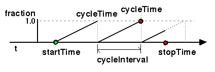
No guarantees are made with respect to how often a TimeSensor node generates time events, but a TimeSensor node shall generate events at least at every simulation tick. TimeSensor nodes are guaranteed to generate final time and fraction_changed events. If loop is FALSE at the end of the Nth cycleInterval and was TRUE at startTime + M × cycleInterval for all 0 < M < N, then the final time event will be generated with a value of (startTime + N × cycleInterval) or stopTime (if stopTime > startTime), whichever value is less. If loop is TRUE at the completion of every cycle, the final event is generated as evaluated at stopTime (if stopTime > startTime) or never.
An active TimeSensor node ignores set_cycleInterval and set_startTime events. An active TimeSensor node also ignores set_stopTime events for set_stopTime <= startTime. For example, if a set_startTime event is received while a TimeSensor node is active, that set_startTime event is ignored (the startTime field is not changed, and a startTime_changed eventOut is not generated). If an active TimeSensor node receives a set_stopTime event that is less than the current time, and greater than startTime, it behaves as if the stopTime requested is the current time and sends the final events based on the current time (note that stopTime is set as specified in the eventIn).
Ignoring set_ events while a TimeSensor is running makes creating simple animations much easier, because for most simple animations you want the animation played to completion before it can be restarted. If you do need to stop and restart a TimeSensor while it is running, send it both a stopTime and a startTime event. The stopTime event will stop the sensor and the startTime event will restart it immediately. For example, this fragment will result in the TimeSensor immediately restarting when the TouchSensor is activated:
     DEF TOUCHS TouchSensor { ... }
     DEF TIMES TimeSensor { ... }
     ROUTE TOUCHS.touchTime TO TIMES.set_stopTime
     ROUTE TOUCHS.touchTime TO TIMES.set_startTime
There are two cases of the TimeSensor that are most common. The first case uses a TimeSensor to drive a single cycle of an animation or behavior. Typically, another node that has a SFTime eventOut (e.g., Script, TouchSensor, or ProximitySensor) routes to the TimeSensor's startTime eventIn (setting it to now or now + delay), which in turn routes its fraction_changed eventOut to another node's set_fraction eventIn.
The second common case of a TimeSensor is a continuously looping animation or behavior. In this case, the TimeSensor's loop field is TRUE, stopTime is 0, startTime is 0, and cycleTime is the length of the intended sequence. This has the effect of starting the sequence in 1970 and looping forever. Be aware that looping TimeSensors can slow down rendering performance if too many are active simultaneously, and should be used only when necessary. It is recommended that you restrict the effect of looping TimeSensors by coupling them with a ProximitySensor, VisibilitySensor, Script, or LOD that disables the TimeSensor when out of range or not relevant.
The following example illustrates the TimeSensor (see Figure 3-62). The first TimeSensor defines a continuously running animation that is enabled and disabled by a ProximitySensor. The second TimeSensor is triggered by a TouchSensor and fires one cycle of an animation each time it is triggered:
#VRML V2.0 utf8
Group { children [
  DEF PS ProximitySensor { size 30 30 30 }
  DEF TS1 TimeSensor {
    enabled FALSE
    loop TRUE
  }
  DEF T1 Transform {
    translation 0 0 -.5
    rotation .707 -.707 0 1.57
    children Shape {
      geometry Box {}
      appearance DEF A Appearance {
        material Material { diffuseColor 1 1 1 }
      }
    }
  }
  DEF OI OrientationInterpolator {
    key [ 0, 0.33, 0.66, 1.0 ]
    keyValue [ .707 .707 0 0,    .707 .707 0 2.09,
               .707 .707 0 4.18, .707 .707 0 6.28 ]
  }
  DEF T2 Transform {
    translation -4 0 0
    children [
      Shape {
        geometry Sphere { radius 0.5 }
        appearance USE A
      }
      DEF TOS TouchSensor {}
      DEF TS2 TimeSensor { cycleInterval 0.75 }
      DEF PI PositionInterpolator {
        key [ 0, .2, .5, .8, 1 ]
        keyValue [ -4 0 0, 0 4 0, 4 0 0, 0 -4 0, -4 0 0 ]
      }
    ]
  }
  Viewpoint { position 0 0 50 description "Animation off"}
  Viewpoint { position 0 0 10 description "Animation on"}
] }
ROUTE PS.isActive TO TS1.enabled
ROUTE TS1.fraction_changed TO OI.set_fraction
ROUTE OI.value_changed TO T1.rotation
ROUTE TOS.touchTime TO TS2.startTime
ROUTE TS2.fraction_changed TO PI.set_fraction
ROUTE PI.value_changed TO T2.translation
![]()
TouchSensor {
  exposedField SFBool  enabled TRUE
  eventOut     SFVec3f hitNormal_changed
  eventOut     SFVec3f hitPoint_changed
  eventOut     SFVec2f hitTexCoord_changed
  eventOut     SFBool  isActive
  eventOut     SFBool  isOver
  eventOut     SFTime  touchTime
}
A TouchSensor node tracks the location and state of the pointing device and detects when the user points at geometry contained by the TouchSensor node's parent group. A TouchSensor node can be enabled or disabled by sending it an enabled event with a value of TRUE or FALSE. If the TouchSensor node is disabled, it does not track user input or send events.
TouchSensor was originally called ClickSensor, and was specified in a "mouse-centric" way. Sam Denton rewrote this section so that it was easier to map alternative input devices (e.g., 3D wands and gloves) into the semantics of the TouchSensor.
The TouchSensor generates events when the pointing device points toward any geometry nodes that are descendants of the TouchSensor's parent group. See "2.6.7.5 Activating and manipulating sensors" for more details on using the pointing device to activate the TouchSensor.
The isOver eventOut reflects the state of the pointing device with regard to whether it is pointing towards the TouchSensor node's geometry or not. When the pointing device changes state from a position such that its bearing does not intersect any of the TouchSensor node's geometry to one in which it does intersect geometry, an isOver TRUE event is generated. When the pointing device moves from a position such that its bearing intersects geometry to one in which it no longer intersects the geometry, or some other geometry is obstructing the TouchSensor node's geometry, an isOver FALSE event is generated. These events are generated only when the pointing device has moved and changed `over' state. Events are not generated if the geometry itself is animating and moving underneath the pointing device.
The isOver event makes it easy to implement a technique called locate highlighting. Locate highlighting means making an active user interface widget change color or shape when the mouse moves over it, and lets the user know that something will happen if they press the mouse button. User interaction inside a 3D scene is something with which users are not familiar, and they probably will not be able to tell which objects are"hot" and which are just decoration just by looking at the scene. Writing a Script that takes isOver events and changes the geometry's color (or activates a Switch that displays a "Click Me" message on top of the sensor's geometry, or starts a Sound of some kind, or does all three!) will make user interaction much easier and more fun for the user.
As the user moves the bearing over the TouchSensor node's geometry, the point of intersection (if any) between the bearing and the geometry is determined. Each movement of the pointing device, while isOver is TRUE, generates hitPoint_changed, hitNormal_changed and hitTexCoord_changed events. hitPoint_changed events contain the 3D point on the surface of the underlying geometry, given in the TouchSensor node's coordinate system. hitNormal_changed events contain the surface normal vector at the hitPoint. hitTexCoord_changed events contain the texture coordinates of that surface at the hitPoint.
The combination of isActive and isOver gives four possible states in which a TouchSensor can exist:
If isOver is TRUE, the user may activate the pointing device to cause the TouchSensor node to generate isActive events (e.g., by pressing the primary mouse button). When the TouchSensor node generates an isActive TRUE event, it grabs all further motion events from the pointing device until it is released and generates an isActive FALSE event (other pointing-device sensors will not generate events during this time). Motion of the pointing device while isActive is TRUE is termed a "drag." If a 2D pointing device is in use, isActive events reflect the state of the primary button associated with the device (i.e., isActive is TRUE when the primary button is pressed and FALSE when it is released). If a 3D pointing device is in use, isActive events will typically reflect whether the pointing device is within (or in contact with) the TouchSensor node's geometry.
The eventOut field touchTime is generated when all three of the following conditions are true:
Further information about this behaviour may be found in "2.6.7.3 Pointing-device sensors", "2.6.7.4 Drag sensors", and "2.6.7.5 Activating and manipulating sensors."
TouchSensor is designed to be abstract enough to apply to a variety of input devices (e.g., wand, glove) and simple enough for the lowest common denominator hardware found on general-purpose computers today--a pointing device with a single button. The success of Apple's Macintosh proves that multiple buttons aren't necessary to create a really good user interface, and since minimalism was one of the design goals for VRML 2.0, only one-button support is required.
The following example illustrates the TouchSensor. The first TouchSensor is used to move a small Box on the surface of a Sphere. The TouchSensor's hitPoint_changed eventOut is routed to the translation field of the Transform affecting the Box. This has the net effect of translating the Box to the intersection point with the TouchSensor's geometry, the Sphere. Note, however, that the second TouchSensor is used as a toggle button to activate and deactivate the first TouchSensor. This is accomplished with a simple Script node that is routed to the first TouchSensor's enabled field. The Switch nodes are used to change the color of the toggle button (Cone) and the Box, based on the activation state (on or off):
#VRML V2.0 utf8
Transform { children [
  Transform { children [
    # Sphere on which the box is moved.
    DEF TOS1 TouchSensor { enabled FALSE }
    Shape {
      geometry Sphere {}
      appearance Appearance {
        material Material { diffuseColor 1 0 1 }
      }
    }
  ]}
  DEF T1 Transform { children [
    # Box that moves and changes activation color.
    DEF SW1 Switch {
      whichChoice 0
      choice [
        Shape {   # choice 0 = off state
          geometry DEF B Box { size 0.25 0.25 0.25 }
          appearance Appearance {
            material Material { diffuseColor 0.2 0.2 0 }
          }
        }
        Shape {   # choice 1 = on state
          geometry USE B
          appearance Appearance {
            material Material { diffuseColor 1 1 0.2 }
          }
        }
      ]
    }
  ]}
  Transform {
    # toggle button which turns box on/off.
    translation -3 0 0
    children [
      DEF TOS2 TouchSensor {}
      DEF SW2 Switch {
        whichChoice 0
        choice [
          Shape {   # choice 0 = off state
            geometry DEF C Cone {}
            appearance Appearance {
              material Material { diffuseColor 0.8 0.4 0.4 }
            }
          }
          Shape {   # choice 1 = on state
            geometry USE C
            appearance Appearance {
              material Material { diffuseColor 1.0 0.2 0.2 }
            }
          }
        ]
      }
      DEF S2 Script {
        eventIn SFTime touchTime
        field SFBool enabled FALSE
        eventOut SFBool onOff_changed
        eventOut SFInt32 which_changed
        url "javascript:
          function initialize() {
            // Initialize to off state.
            whichChoice = 0;
            onOff_changed = false;
          }
          function touchTime( value, time ) {
            # Toggle state on each click.
            enabled = !enabled;
            onOff_changed = enabled;
            which_changed = enabled;
          }"
      }
    ]
  }
]}
ROUTE TOS2.touchTime TO S2.touchTime
ROUTE S2.onOff_changed TO TOS1.enabled
ROUTE S2.which_changed TO SW1.whichChoice
ROUTE S2.which_changed TO SW2.whichChoice
ROUTE TOS1.hitPoint_changed TO T1.set_translation
![]()
Transform {
  eventIn      MFNode      addChildren
  eventIn      MFNode      removeChildren
  exposedField SFVec3f     center           0 0 0    # (-,)
  exposedField MFNode      children         []
  exposedField SFRotation  rotation         0 0 1 0  # [-1,1],(-,)
  exposedField SFVec3f     scale            1 1 1    # (0,)
  exposedField SFRotation  scaleOrientation 0 0 1 0  # [-1,1],(-,)
  exposedField SFVec3f     translation      0 0 0    # (-,)
  field        SFVec3f     bboxCenter       0 0 0    # (-,)
  field        SFVec3f     bboxSize         -1 -1 -1 # (0,) or -1,-1,-1
}
The Transform node is a grouping node that defines a coordinate system for its children that is relative to the coordinate systems of its ancestors. See sections "2.4.4 Transformation hierarchy" and "2.4.5 Standard units and coordinate system" for a description of coordinate systems and transformations.
"2.6.5 Grouping and children nodes" provides a description of the children, addChildren, and removeChildren fields and eventIns.
The bboxCenter and bboxSize fields specify a bounding box that encloses the children of the Transform node. This is a hint that may be used for optimization purposes. If the specified bounding box is smaller than the actual bounding box of the children at any time, the results are undefined. A default bboxSize value, (-1, -1, -1), implies that the bounding box is not specified and, if needed, must be calculated by the browser. A description of the bboxCenter and bboxSize fields is provided in "2.6.4 Bounding boxes."
The translation, rotation, scale, scaleOrientation and center fields define a geometric 3D transformation consisting of (in order):
The center field specifies a translation offset from the origin of the local coordinate system (0,0,0). The rotation field specifies a rotation of the coordinate system. The scale field specifies a non-uniform scale of the coordinate system. scale values shall be > 0.0. The scaleOrientation specifies a rotation of the coordinate system before the scale (to specify scales in arbitrary orientations). The scaleOrientation applies only to the scale operation. The translation field specifies a translation to the coordinate system.
The translation/rotation/scale operations performed by the Transform node occur in the "natural" order—each operation is independent of the other. For example, if the Transform's translation field is (1, 0, 0), then the objects underneath the Transform will be translated one unit to the right, regardless of the Transform's rotation and scale fields. If you want to apply a series of translate/rotate/scale operations in some other order, you can either use nested Transform nodes or figure out the combined transformation and express that as a single Transform node. As long as all of your scaling operations are uniform scales (scale equally about x-, y-, z-axes), then any series of scale/rotate/translate operations can be expressed as a single Transform node.
Note that negative scale values are not allowed, so the common trick of defining one-half of an object and then mirroring it (using a negative scale and USE-ing the geometry again) will not work. Interactive programs will still provide mirroring operations, of course, but when saving to a VRML file the program will have to duplicate the mirrored polygons to avoid the negative scale.
Given a 3-dimensional point P and Transform node, P is transformed into point P' in its parent's coordinate system by a series of intermediate transformations. In matrix transformation notation, where C (center), SR (scaleOrientation), T (translation), R (rotation), and S (scale) are the equivalent transformation matrices,
P' = T × C × R × SR × S × -SR × -C × P
The following Transform node:
Transform {
    center           C
    rotation         R
    scale            S
    scaleOrientation SR
    translation      T
    children         [...]
}
is equivalent to the nested sequence of:
Transform {
  translation T
  children Transform {
    translation C
    children Transform {
      rotation R
      children Transform {
        rotation SR
        children Transform {
          scale S
          children Transform {
            rotation -SR
            children Transform {
              translation -C
              children [...]
}}}}}}}
VRML 1.0 included special-purpose versions of Transform—Scale, Rotate, and Translate nodes—and the more general MatrixTransform node. The special-purpose nodes were dropped from VRML 2.0 because they are equivalent to a Transform node with some of its fields left as default values. If their absence bothers you, their prototype definitions are trivial. For example:
     PROTO Translate [ exposedField SFVec3f translation ] {
       Transform { translation IS translation }
     }
Dropping MatrixTransform was much more controversial. Allowing arbitrary matrix transformations was a very powerful feature that is almost impossible to support in its full generality. The arbitrary 4×4 matrix of the MatrixTransform allows specification of perspective transformations that have singularities and degenerate matrices that cannot be inverted, both of which cause major implementation headaches. Lighting operations, for example, typically rely on transforming normal vectors by the inverse transpose of the transformation matrix, which is a big problem if the matrix cannot be inverted. And picking operations (determining which geometry is underneath the pointing device) are best done by transforming a picking ray into the object's coordinate space, which, again, is impossible if there is a degenerate or perspective transformation in the transformation stack. No VRML 1.0 browser completely implements the MatrixTransform node.
Restricting the legal values of a MatrixTransform was suggested, but doing that makes MatrixTransform just another representation for the Transform node. Since that representation is both more verbose (16 numbers, four of which would always be (0, 0, 0, 1) versus the ten for a simple translate/rotate/scale Transform node), conversion back and forth between the two representations is possible (see the Graphics Gems series of books by Academic Press for several approaches). MatrixTransform was used in relatively few VRML 1.0 worlds, and one of the design goals for VRML 2.0 was minimalism. For all of these reasons, MatrixTransform is not part of the VRML 2.0 specification.
To use the Transform node properly, it is important to understand the order of the transformation operations as they accumulate. The first step is the center field. It translates the local origin of the object to a new position before all the other operations take place. It does not translate the object and will have no effect if no other operations are specified. Think of this operation as specifying the location of the object's center point to be used for subsequent operations (e.g., rotation). For example, the default Box node is centered at (0,0,0), and represents a cube that spans -1 to +1 along all three axes. In the following file excerpt, the Box is parented by a Transform that specifies a center of (-3,0,0) and a rotation of +180 degrees about the Z-axis of the modified center. The result is an upside-down box centered at (-6,0,0):
     Transform {
       center -3 0 0
       rotation 0 0 1 3.14
       children Shape { geometry Box {} }
     }
The second operation, in order, is the scaleOrientation. This operation is the most obscure and is rarely used. The scaleOrientation temporarily rotates the object's coordinate system (i.e., local origin) in preparation for the third operation, scale, and rotates back after the scale is performed. This is sometimes handy when you wish to scale your object along a direction that is not aligned with the object's local coordinate system (e.g., skewing).
The fourth operation is rotation. It specifies an axis about which to rotate the object and the angle (in radians) to rotate. Remember that positive rotations produce counterclockwise rotations when viewed down the positive axis. This is sometimes referred to as the right-hand rule (see any computer graphics or VRML tutorial book for an explanation).
The last operation is translation. It specifies a translation to be applied to the object. Remember that translation will occur along the local axes of the object's coordinate-system.
Another important concept to understand is the order in which nested Transforms operate. Within a single Transform the operation order occurs as described, but when a Transform parents another Transform, the lowest level Transform is applied first and each subsequent parent's operations are applied in "upward" order. For example, the following excerpt defines two Transforms, T1 and T2. The first Transform, T1, performs a translation and a scale operation, and has a child T2. The Transform T2 performs a scale and a rotation operation. Therefore, the order of operations is: T2 scale, T2 rotation, T1 scale, and finally T1 translation. It is important to notice that T1's scale operation scales the rotated object (and produces a skew):
     DEF T1 Transform {
       scale 1 2 1                  # Stretch along Y
       translation 0 0 -3           # Translate back in Z
       children DEF T2 Transform {
         scale  1 1 10              # Stretch in Z
         rotation 1 0 0 0.785       # Rotate 45 degrees about X axis
         children Shape { geometry Box {} }
       }
     }
The following example illustrates the Transform node. The first Transform, T1, is the parent transformation for all subsequent objects in the file. The second Transform, T2, uses default values and is transformed by its parent's transformations. The third Transform, T3, specifies a new center point and a rotation about that center point. Note that these operations take place before the T1's scale and translation. The fourth Transform, T4, scales and translates the object, and of course is also transformed by T1.
#VRML V2.0 utf8
DEF T1 Transform {        # Parent transform for entire file
  translation 0 0 -100    # Translates entire file down Z
  scale 1 2 1             # Scales entire file in Y
  children [
    DEF T2 Transform {    # Default transform at origin
      children Shape {
        geometry Box {}
        appearance Appearance {
          material Material { diffuseColor 1 0 0 }
    }}}
    DEF T3 Transform {     # Re-centered and rotated
      center -3 0 0
      rotation 0 0 1 3.14
      children Shape {
        geometry Cone {}
        appearance Appearance {
          material Material { diffuseColor 0 1 0 }
    }}}
    DEF T4 Transform {     # Scaled (half) and translated +X
      scale 0.5 0.5 0.5
      translation 3 0 0
      children Shape {
        geometry Cylinder {}
        appearance Appearance {
          material Material { diffuseColor 0 0 1 }
    }}}
  ]
}
![]()
Viewpoint {
  eventIn      SFBool     set_bind
  exposedField SFFloat    fieldOfView    0.785398  # (0,)
  exposedField SFBool     jump           TRUE
  exposedField SFRotation orientation    0 0 1 0   # [-1,1],(-,)
  exposedField SFVec3f    position       0 0 10    # (-,)
  field        SFString   description    ""
  eventOut     SFTime     bindTime
  eventOut     SFBool     isBound
}
The Viewpoint node defines a specific location in the local coordinate system from which the user may view the scene. Viewpoint nodes are bindable children nodes (see "2.6.10 Bindable children nodes") and thus there exists a Viewpoint node stack in the browser in which the top-most Viewpoint node on the stack is the currently active Viewpoint node. If a TRUE value is sent to the set_bind eventIn of a Viewpoint node, it is moved to the top of the Viewpoint node stack and activated. When a Viewpoint node is at the top of the stack, the user's view is conceptually re-parented as a child of the Viewpoint node. All subsequent changes to the Viewpoint node's coordinate system change the user's view (e.g., changes to any ancestor transformation nodes or to the Viewpoint node's position or orientation fields). Sending a set_bind FALSE event removes the Viewpoint node from the stack and produces isBound FALSE and bindTime events. If the popped Viewpoint node is at the top of the viewpoint stack, the user's view is re-parented to the next entry in the stack. More details on binding stacks can be found in "2.6.10 Bindable children nodes." When a Viewpoint node is moved to the top of the stack, the existing top of stack Viewpoint node sends an isBound FALSE event and is pushed down the stack.
Viewpoints follow the binding stack paradigm because they are like a global property—the viewer's position and orientation are determined by, at most, one Viewpoint at a time.
It may seem strange that the viewer's position or orientation is changed by binding to and then modifying a Viewpoint, but a completely different node (ProximitySensor) is used to determine the viewer's current position or orientation. This asymmetry makes sense, because reporting the viewer's position and orientation is not like a global property. The viewer's position and orientation can be reported in any local coordinate system, and there may be multiple Scripts tracking the movements of the viewer at the same time.
An author can automatically move the user's view through the world by binding the user to a Viewpoint node and then animating either the Viewpoint node or the transformations above it. Browsers shall allow the user view to be navigated relative to the coordinate system defined by the Viewpoint node (and the transformations above it) even if the Viewpoint node or its ancestors' transformations are being animated.
If you want to control completely how the viewer may move through your world, bind to a NavigationInfo node that has its type field set to NONE. When the navigation type is NONE, browsers should remove all out-of-scene navigation controls and not allow the user to move away from the currently bound Viewpoint.
The bindTime eventOut sends the time at which the Viewpoint node is bound or unbound. This can happen:
The position and orientation fields of the Viewpoint node specify relative locations in the local coordinate system. Position is relative to the coordinate system's origin (0,0,0), while orientation specifies a rotation relative to the default orientation. In the default position and orientation, the user is on the Z-axis looking down the -Z-axis toward the origin with +X to the right and +Y straight up. Viewpoint nodes are affected by the transformation hierarchy.
Navigation types (see "3.29 NavigationInfo") that require a definition of a down vector (e.g., terrain following) shall use the negative Y-axis of the coordinate system of the currently bound Viewpoint node. Likewise navigation types that require a definition of an up vector shall use the positive Y-axis of the coordinate system of the currently bound Viewpoint node. The orientation field of the Viewpoint node does not affect the definition of the down or up vectors. This allows the author to separate the viewing direction from the gravity direction.
The distinction between the gravity direction (which way is down) and the Viewpoint's orientation (which way the user happens to be looking) allows you to create interesting effects, but also requires you to be careful when animating Viewpoint orientations. For example, if you create an animation that moves the viewer halfway up a mountain, with the final orientation looking up toward the top of the mountain, you should animate the fields of the Viewpoint and not a Transform node above the Viewpoint. If you do animate the coordinate system of the Viewpoint (a Transform node above it), then you are changing the down direction, and if the user happens to step off a bridge over a chasm you placed on the mountain, they will fall in the wrong direction. Note that all of this is assuming that the VRML browser being used implements terrain following--keeping users on the ground as they move around the world. Although not required by the VRML specification, it is expected that most VRML browsers will support terrain following because it makes moving through a 3D world so much easier.
The jump field specifies whether the user's view "jumps" to the position and orientation of a bound Viewpoint node or remains unchanged. This jump is instantaneous and discontinuous in that no collisions are performed and no ProximitySensor nodes are checked in between the starting and ending jump points. If the user's position before the jump is inside a ProximitySensor the exitTime of that sensor shall send the same timestamp as the bind eventIn. Similarly, if the user's position after the jump is inside a ProximitySensor the enterTime of that sensor shall send the same timestamp as the bind eventIn. Regardless of the value of jump at bind time, the relative viewing transformation between the user's view and the current Viewpoint node shall be stored with the current Viewpoint node for later use when un-jumping (i.e., popping the the Viewpoint node binding stack from a Viewpoint node with jump TRUE). The following summarizes the the bind stack rules (described in "2.6.10 Bindable children nodes") with additional rules regarding Viewpoint nodes (displayed in boldface type):
The jump field may change after a Viewpoint node is bound. The rules described above still apply. If jump was TRUE when the Viewpoint node is bound, but changed to FALSE before the set_bind FALSE is sent, the Viewpoint node does not un-jump during unbind. If jump was FALSE when the Viewpoint node is bound, but changed to TRUE before the set_bind FALSE is sent, the Viewpoint node does perform the un-jump during unbind.
Note that there are two other mechanisms that result in the binding of a new Viewpoint:
Both of these mechanisms override the jump field value of the specified Viewpoint node (#ViewpointName) and assume that jump is TRUE when binding to the new Viewpoint. The behavior of the viewer transition to the newly bound Viewpoint depends on the currently bound NavigationInfo node's type field value (see "3.29 NavigationInfo").
The rules for properly implementing the jump field are pretty complicated, but it is really a pretty simple concept. If jump is TRUE, then the viewer will be teleported to the Viewpoint as soon as the Viewpoint is bound (they will jump there instantaneously). If jump is FALSE, then the viewer will not appear to move at all when the Viewpoint is bound; the viewer will move only when the Viewpoint changes.
Discontinuous movements can be disorienting for the user. It is as if they are suddenly blindfolded, taken to another place, and unblindfolded. It is generally better to animate viewers to a new location smoothly so that they have a sense of where they are relative to where they were. Combining a Viewpoint with its jump field set to FALSE with a ProximitySensor to detect the user's position and orientation, and some interpolators to move the viewer smoothly to a new position and orientation, is a good technique. For example, here is a prototype that will smoothly move the user to a new position and orientation at a given startTime:
     #VRML V2.0 utf8
     PROTO SmoothMove [ exposedField SFTime howLong 1
                        eventIn SFTime set_startTime
                        field SFVec3f newPosition 0 0 0
                        field SFRotation newOrientation 0 0 1 0 ]
     {
       # Group is just a convenient way of holding the necessary
       # ProximitySensor and Viewpoint:
       Group {
         children [
           # ProximitySensor to detect where the user is.
           DEF PS ProximitySensor { size 1e10 1e10 1e10 }
           # This Viewpoint is bound when the TimeSensor goes active,
           # animated, and then unbound when the TimeSensor finishes.
           DEF V Viewpoint { jump FALSE }
         ]
       }
       # TimeSensor drives the interpolators to give smooth animation.
       DEF TS TimeSensor {
         set_startTime IS set_startTime
         cycleInterval IS howLong
       }
       DEF PI PositionInterpolator {
         key [ 0, 1 ]
         # These are dummy keyframes; real keyframes set by Script node
         # when the TimeSensor becomes active.
         keyValue [ 0 0 0, 0 0 0 ]
       }
       DEF OI OrientationInterpolator {
         key [ 0, 1 ]
         keyValue [ 0 0 1 0,  0 0 1 0 ]
       }
       DEF S Script {
         field SFVec3f newPosition IS newPosition
         field SFRotation newOrientation IS newOrientation
         field SFNode p_sensor USE PS
         eventIn SFTime startNow
         eventOut MFVec3f positions
         eventOut MFRotation orientations
         url "javascript:
           function startNow() {
             // Starting: setup interpolators (direct ROUTE from
             // TimeSensor.isActive to Viewpoint.set_bind binds the
             // Viewpoint for us)

             positions[0] = p_sensor.position_changed;
             positions[1] = newPosition;
             orientations[0] = p_sensor.orientation_changed;
             orientations[1] = newOrientation;
           }"
       }
       ROUTE TS.isActive TO V.set_bind
       ROUTE TS.fraction_changed TO PI.set_fraction
       ROUTE TS.fraction_changed TO OI.set_fraction
       ROUTE OI.value_changed TO V.set_orientation
       ROUTE TS.cycleTime TO S.startNow
       ROUTE S.positions TO PI.keyValue
       ROUTE S.orientations TO OI.keyValue
       ROUTE PI.value_changed TO V.set_position
     }
     # Example use:  Touch cube, move to new position/orientation
     Group {
       children [
         Shape {
           appearance Appearance { material
             Material { diffuseColor 0.8 0.2 0.4 }
           }
           geometry Box { }
         }
         DEF SM SmoothMove {
           howLong 5
           newPosition 0 0 10
           newOrientation 0 1 0  .001
         }
         DEF TS TouchSensor { }
       ]
     }
     ROUTE TS.touchTime TO SM.set_startTime
The fieldOfView field specifies a preferred minimum viewing
angle from this viewpoint in radians. A small field-of-view roughly
corresponds to a telephoto lens; a large field-of-view roughly
corresponds to a wide-angle lens. The field-of-view shall be greater
than zero and smaller than ![]() . The value of fieldOfView represents
the minimum viewing angle in any direction axis perpendicular to the
view. For example, a browser with a rectangular viewing projection
shall have the following relationship:
. The value of fieldOfView represents
the minimum viewing angle in any direction axis perpendicular to the
view. For example, a browser with a rectangular viewing projection
shall have the following relationship:
      display width    tan(FOVhorizontal/2)
      -------------- = -----------------
      display height   tan(FOVvertical/2)
where the smaller of display width or display height determines which
angle equals the fieldOfView (the larger angle is computed using
the relationship described above). The larger angle shall not exceed ![]() and
may force the smaller angle to be less than fieldOfView in order
to sustain the aspect ratio.
and
may force the smaller angle to be less than fieldOfView in order
to sustain the aspect ratio.
A small field-of-view is like a telephoto lens on a camera and will make distant objects look bigger. Changing the field-of-view can give interesting effects, but browsers may choose to implement a fixed field-of-view for the very good reason that display devices such as head-mounted displays have an inherent field-of-view and overriding it can result in the user becoming disoriented or even sick. If you want to zoom in on some part of your world, it is better to move the Viewpoint closer rather than changing its field-of-view.
The description field specifies a textual description of the Viewpoint node. This may be used by browser-specific user interfaces. If a Viewpoint's description field is empty it is recommended that the browser not present this Viewpoint in its browser-specific user interface.
The URL syntax ".../scene.wrl#ViewpointName" specifies the user's initial view when loading "scene.wrl" to be the first Viewpoint node in the file that appears as DEF ViewpointName Viewpoint {...}. This overrides the first Viewpoint node in the file as the initial user view, and a set_bind TRUE message is sent to the Viewpoint node named "ViewpointName". If the Viewpoint node named "ViewpointName" is not found, the browser shall use the first Viewpoint node in the file (i.e. the normal default behaviour). The URL syntax "#ViewpointName" (i.e. no file name) specifies a viewpoint within the existing file. If this URL is loaded (e.g. Anchor node's url field or loadURL() method is invoked by a Script node), the Viewpoint node named "ViewpointName" is bound (a set_bind TRUE event is sent to this Viewpoint node).
This "#name" URL syntax comes directly from HTML, where specifying a URL of the form page.html#name jumps to a specific (named) location in a given page.
The easiest way to move the viewer between viewpoints in the world is to use an Anchor node and the #ViewpointName URL syntax. For example, this VRML file format fragment will take users to the viewpoint named MOUNTAIN_TOP when they click on the Box:
     Anchor {
       children Shape {
         appearance Appearance {
           material Material { }
         }
         geometry Box { }
       }
       url "#MOUNTAIN_TOP"
     }
If a Viewpoint node is bound and is the child of an LOD, Switch, or any node or prototype that disables its children, the result is undefined. If a Viewpoint node is bound that results in collision with geometry, the browser shall perform its self-defined navigation adjustments as if the user navigated to this point (see Collision).
You will almost always want to name a Viewpoint node using DEF, because Viewpoints don't do much by themselves. You will either ROUTE events to them or will use the URL #ViewpointName syntax.
You should be careful when you use the USE feature with Viewpoints. USE can make the same object appear in multiple places in the world at the same time. For example, you might create just a few different cars and then USE them many times to create a traffic jam. However, what would happen if you put a Viewpoint named "DRIVER" inside one of the cars and then bound the viewer to that Viewpoint? The car would be in multiple places in the world at the same time--something that is OK for a virtual world, but can never happen in the real world. And since the person looking at the virtual world is a real person who can look at the virtual world from only one place at a time, there is a problem. What happens is undefined. Browsers can do whatever they wish, including completely ignoring the DRIVER Viewpoint or randomly picking one of the locations of the car and putting the viewer there.
To avoid problems, you should make sure that each Viewpoint is the child of exactly one grouping node. And that any of the Viewpoint's parent grouping nodes is the child of only one grouping node, too.
The following example illustrates the Viewpoint node. This example demonstrates a couple of typical uses of Viewpoints. Click on one of the shapes (Box, Cone, Sphere) to move yourself to a Viewpoint on their platform. Navigate yourself onto the moving white platform, which will then bind you to a Viewpoint on that platform and move you along with it. Move off the platform to unbind yourself from that Viewpoint:
#VRML V2.0 utf8
# Three fixed viewpoints
DEF V1 Viewpoint {
  position 0 1.8 -12
  orientation 0 1 0  3.1416
  description "View: green platform"
}
DEF V2 Viewpoint {
  position -10.4 1.8 6
  orientation 0 1 0  -1.047
  description "View: red platform"
}
DEF V3 Viewpoint {
  position 10.4 1.8 6
  orientation 0 1 0  1.047
  description "View: blue platform"
}
# A moving Viewpoint.  This Transform rotates, taking the
# Viewpoint, ProximitySensor and children with it:
DEF VT Transform { children [
  Transform {
    translation 0 -.1 -4
    children [
      DEF V4 Viewpoint {
        position 0 1.3 1.8      # Edge of platform
        orientation 0 1 0  0  # Looking out
        jump FALSE
        description "View: moving platform"
      }
      Shape {  # Octagonal platform
        appearance Appearance { material Material { } }
        geometry  IndexedFaceSet {
          coord Coordinate {
            point [ 1 0 2, 2 0 1, 2 0 -1, 1 0 -2,
                    -1 0 -2, -2 0 -1, -2 0 1, -1 0 2 ]
          }
          coordIndex [ 0, 1, 2, 3, 4, 5, 6, 7, -1 ]
        }
      }
      # When this ProximitySensor is activated, viewer bound to V4:
      DEF PS ProximitySensor {
        center 0 2 0
        size 4 4 4
      }
    ]
  }
  DEF OI OrientationInterpolator {
    # It takes 18 seconds to go all the way around.
    # Four-second 120-degree rotation, two second pause, repeated
    # three times.
    # These keytimes are 18'ths:
    key [ 0,    .056, .167, .22,
          .33,  .389, .5,   .556,
          .667, .722, .833, .889,
          1 ]
    # Rotate a total of 2 PI radians.  Keys are given at 1/8 and 7/8
    # of each one-third rotation to make the rot smoother (slow
    # in-out animation); that's why these angles are multiples of
    # 1/24'th (PI/12 radians) rotation:
    keyValue [
      0 1 0  0,      0 1 0  .262,   0 1 0  1.833,  0 1 0  2.094,
      0 1 0  2.094,  0 1 0  2.356,  0 1 0  3.927,  0 1 0  4.189,
      0 1 0  4.189,  0 1 0  4.45,   0 1 0  6.021,  0 1 0  0,
      0 1 0  0
    ]
  }
  DEF TS TimeSensor {
    loop TRUE  startTime 1
    cycleInterval 18
  }
]}
#Routes for platform animation:
ROUTE TS.fraction_changed TO OI.set_fraction
ROUTE OI.value_changed TO VT.set_rotation
# And bind viewer to V4 when they're on the moving platform:
ROUTE PS.isActive TO V4.set_bind
# Some geometry to look at:
DirectionalLight { direction 0 -1 0 }
Transform {
  translation 0 0 -9
  children [
    Shape {
      appearance DEF A1 Appearance {
        material Material { diffuseColor 0 0.8 0 }
      }
      geometry DEF IFS IndexedFaceSet {
        coord Coordinate {
          point [ 0 0 -6, -5.2 0 3,  5.2 0 3 ]
        }
        coordIndex [ 0, 1, 2, -1 ]
        solid FALSE
      }
    }
    Anchor {
      url "#V1"
      children
      Transform {
        translation 0 0.5 0
        children Shape {
          appearance USE A1
          geometry Box { size 1 1 1 }
        }
}}]}
Transform {
  translation -7.8 0 4.5
  children [
    Shape {
      geometry USE IFS
      appearance DEF A2 Appearance {
        material Material { diffuseColor 0.8 0 0 }
    }}
    Anchor {
      url "#V2"
      children Transform {
        translation 0 .5 0
        children Shape {
          appearance USE A2
          geometry Sphere { radius .5 }
}}}]}
Transform {
  translation 7.8 0 4.5
  children [
    Shape {
      geometry USE IFS
      appearance DEF A3 Appearance {
        material Material { diffuseColor 0 0 0.8 }
      }
    }
    Anchor {
      url "#V3"
      children Transform {
        translation 0 .5 0
        children Shape {
          appearance USE A3
          geometry Cone { bottomRadius .5  height 1 }
}}}]}
![]()
VisibilitySensor {
  exposedField SFVec3f center   0 0 0      # (-,)
  exposedField SFBool  enabled  TRUE
  exposedField SFVec3f size     0 0 0      # [0,)
  eventOut     SFTime  enterTime
  eventOut     SFTime  exitTime
  eventOut     SFBool  isActive
}
The VisibilitySensor node detects visibility changes of a rectangular box as the user navigates the world. VisibilitySensor is typically used to detect when the user can see a specific object or region in the scene in order to activate or deactivate some behaviour or animation. The purpose is often to attract the attention of the user or to improve performance.
A VisibilitySensor detects whether a box-shaped region of the world is visible or not. If you need to find out if an object is visible or not, it is up to you to set the VisibilitySensor's center and size fields so that the VisibilitySensor surrounds the object.
The enabled field enables and disables the VisibilitySensor node. If enabled is set to FALSE, the VisibilitySensor node does not send events. If enabled is TRUE, the VisibilitySensor node detects changes to the visibility status of the box specified and sends events through the isActive eventOut. A TRUE event is output to isActive when any portion of the box impacts the rendered view. A FALSE event is sent when the box has no effect on the view. Browsers shall guarantee that, if isActive is FALSE, the box has absolutely no effect on the rendered view. Browsers may err liberally when isActive is TRUE. For example, the box may affect the rendering.
In other words, it is not OK for a browser to say that something is invisible when it can be seen, but it is OK for a browser to say that something is visible when it actually isn't. The reason the rules are written this way is to allow browser implementors to decide how accurate to make their visibility computations. For example, one implementation might simply calculate whether or not the visibility region is inside or outside the viewer's field-of-view, while another might go further and compute whether or not there is an object in front of the visibility region that completely hides it.
The exposed fields center and size specify the object space location of the box centre and the extents of the box (i.e., width, height, and depth). The VisibilitySensor node's box is affected by hierarchical transformations of its parents. The components of the size field shall be >= 0.0.
The enterTime event is generated whenever the isActive TRUE event is generated, and exitTime events are generated whenever isActive FALSE events are generated.
Each VisibilitySensor node behaves independently of all other VisibilitySensor nodes. Every enabled VisibilitySensor node that is affected by the user's movement receives and sends events, possibly resulting in multiple VisibilitySensor nodes receiving and sending events simultaneously. Unlike TouchSensor nodes, there is no notion of a VisibilitySensor node lower in the scene graph "grabbing" events. Multiply instanced VisibilitySensor nodes (i.e., DEF/USE) use the union of all the boxes defined by their instances. An instanced VisibilitySensor node shall detect visibility changes for all instances of the box and send events appropriately.
The VisibilitySensor node is often ignored yet excellent tool for managing behavior complexity and rendering performance of your scene. Use the VisibilitySensor to disable interpolators or Scripts when not in view. For example, imagine a file that contains several butterfly swarms that flutter around various flower patches (guided by either interpolators or a Script). Each butterfly swarm can be managed by a VisibilitySensor that encloses the entire swarm and disables the swarm movement when out of view. This is also a good technique for building into behavioral objects or prototypes that you intend to reuse in other files. It establishes good composability principles (objects that manage themselves and do not arbitrarily impact overall world performance).
The following illustrates a simple example of a VisibilitySensor. Two TimeSensors are used to move a Cylinder: one gives it a large motion and one gives it a small motion. A VisibilitySensor is used to disable the small-motion TimeSensor when the object is out of view:
#VRML V2.0 utf8
DEF T1 Transform {  # Large motion transform
  children [
    DEF VS VisibilitySensor {
      # Must be big enough to enclose object plus small motion:
      size 1.6 4.6 1.6
    }
    DEF T2 Transform { # Small motion transform
      children [
        Shape {
          appearance Appearance { material Material { } }
          geometry Cylinder { }
        }
      ]
    }
  ]
}
DEF TS1 TimeSensor { # Large motion TimeSensor
  loop TRUE
  cycleInterval 50
}
DEF PI1 PositionInterpolator { # Gross movement around scene
  key [ 0, .1, .2, .3, .4, .5, .6, .7, .8, .9, 1 ]
  keyValue [ 0 0 -30,  -10 5 -20,  -20 0 -10,  -30 -5 10,
             -20 7 20,  -10 4 10,  0 6 20,  20 4 0,  30 2 -20,
             10 0 -20,  0 0 -30 ]
}
ROUTE TS1.fraction_changed TO PI1.set_fraction
ROUTE PI1.value_changed TO T1.set_translation
DEF TS2 TimeSensor { # Small motion
  loop TRUE
  cycleInterval 5
}
DEF PI2 PositionInterpolator { # Fine movement
  key [ 0, .2, .4, .6, .8, 1 ]
  keyValue [ 0 0 0, 0 1 0, 0 2 0, 0 3 0, 0 1.8 0, 0 0 0 ]
}
DEF OI OrientationInterpolator { # More fine movement:
  # One full rotation requires at least 4 keyframes to avoid
  # indeterminate rotation:
  key [ 0, .33, .66, 1 ]
  keyValue [ 1 0 0  0,  1 0 0  2.09,  1 0 0  4.19, 1 0 0  0 ]
}
DEF V Viewpoint {
  description "Initial View"
  position 0 1.6 15
}
ROUTE TS2.fraction_changed TO PI2.set_fraction
ROUTE TS2.fraction_changed TO OI.set_fraction
ROUTE PI2.value_changed TO T2.set_translation
ROUTE OI.value_changed TO T2.set_rotation
# Only perform fine motion when cylinder is visible:
ROUTE VS.isActive TO TS2.set_enabled
![]()
WorldInfo {
  field MFString info  []
  field SFString title ""
}
The WorldInfo node contains information about the world. This node is strictly for documentation purposes and has no effect on the visual appearance or behaviour of the world. The title field is intended to store the name or title of the world so that browsers can present this to the user (perhaps in the window border). Any other information about the world can be stored in the info field, such as author information, copyright, and usage instructions.
You can use WorldInfo nodes to save title, copyright, credit, statistical, and authoring data. This can be included in the final published file or stripped out in the last step. It is recommended that you place this information at the top of the file, so that others notice it. Typically, only the first WorldInfo node in the file specifies the title field. If you have information that applies to a specific object in the file, create a Group node, insert a WorldInfo as the first child in the Group, and add the relevant nodes as subsequent children (see the following example).
The following example illustrates a few simple uses of the WorldInfo node. The first WorldInfo specifies the world's title, overall credits, legal information, and authoring data pertaining to the entire file. The second WorldInfo is used as a lightweight stand-in node for an empty level of an LOD node. The third WorldInfo documents a specific object in the scene (the Cone). In this case, the author has specified that if anyone wishes to reuse this data, they must retain the WorldInfo node and thus give credit to the original author. The third example also illustrates how an authoring system can store technical data for future editing sessions. It is recommended that authors (and authoring systems) strip out this extra data during the publishing step to reduce download time:
#VRML V2.0 utf8
WorldInfo {    # Title and documentation for this file
  title "The Annotated VRML97 Reference Manual world"
  info [ "Copyright (c) 1997 by Rikk Carey and Gavin Bell",
         "Published by Addison-Wesley Publishing Co., Inc.",
         "All rights reserved.  etc.",
         "Created using XYZ Author: version 4.3 ..." ]
}
Group {
  children [
    LOD {
      range [ 10 ]
      level [
        Shape { geometry Sphere { radius 2 } }
        WorldInfo {}        # Empty level standin
      ]
    }
    Group {
      children [
        WorldInfo {          # Documentation for this object
          info [ "DO NOT REMOVE THIS INFORMATION.",
                 "Copyright (c) by John Smith",
                 "The following object was created ...",
                 "Modeling information: x=123.45 y=42, a=666 ...",
                 "Tips: This object is centered at 0,0,0..." ]
        }
        Shape {
          geometry Cone {}
          appearance Appearance { material Material {} }
        }
      ]
    }
  ]
}
![]()