 A Brief History
 A Brief History
Finite Element Analysis (FEA) was first developed in 1943 by R. Courant, who utilized the Ritz method of numerical analysis and minimization of variational calculus to obtain approximate solutions to vibration systems. Shortly thereafter, a paper published in 1956 by M. J. Turner, R. W. Clough, H. C. Martin, and L. J. Topp established a broader definition of numerical analysis. The paper centered on the "stiffness and deflection of complex structures".
By the early 70's, FEA was limited to expensive
mainframe computers generally owned by the aeronautics, automotive,
defense, and nuclear industries. Since the rapid decline in the
cost of computers and the phenomenal increase in computing power,
FEA has been developed to an incredible precision. Present day
supercomputers are now able to produce accurate results for all
kinds of parameters.
What is Finite Element Analysis?
FEA consists of a computer model of a material or design that is stressed and analyzed for specific results. It is used in new product design, and existing product refinement. A company is able to verify a proposed design will be able to perform to the client's specifications prior to manufacturing or construction. Modifying an existing product or structure is utilized to qualify the product or structure for a new service condition. In case of structural failure, FEA may be used to help determine the design modifications to meet the new condition.
There are generally two
types of analysis that are used in industry: 2-D modeling, and
3-D modeling. While 2-D modeling conserves simplicity and allows
the analysis to be run on a relatively normal computer, it tends
to yield less accurate results. 3-D modeling, however, produces
more accurate results while sacrificing the ability to run on
all but the fastest computers effectively. Within each of these
modeling schemes, the programmer can insert numerous algorithms
(functions) which may make the system behave linearly or non-linearly.
Linear systems are far less complex and generally do not take
into account plastic deformation. Non-linear systems do account
for plastic deformation, and many also are capable of testing
a material all the way to fracture.
 How Does Finite Element Analysis Work?
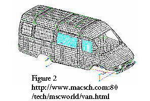
FEA uses a complex system of points called nodes which make a grid called a mesh (Figure 2). This mesh is programmed to contain the material and structural properties which define how the structure will react to certain loading conditions. Nodes are assigned at a certain density throughout the material depending on the anticipated stress levels of a particular area. Regions which will receive large amounts of stress usually have a higher node density than those which experience little or no stress. Points of interest may consist of: fracture point of previously tested material, fillets, corners, complex detail, and high stress areas. The mesh acts like a spider web in that from each node, there extends a mesh element to each of the adjacent nodes. This web of vectors is what carries the material properties to the object, creating many elements. (Theory)
A wide range of objective functions (variables within
the system) are available for minimization or maximization:
There are multiple loading conditions which may be
applied to a system. Next to Figure 3, some examples are shown:
Each FEA program may come with an element library,
or one is constructed over time. Some sample elements are:
Many FEA programs also are equipped with the capability
to use multiple materials within the structure such as:
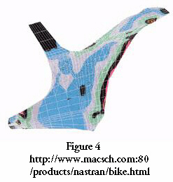
Structural analysis consists of linear and
non-linear models. Linear models use simple parameters and assume
that the material is not plastically deformed. Non-linear models
consist of stressing the material past its elastic capabilities.
The stresses in the material then vary with the amount of deformation
as in Figure 4.
Vibrational analysis is used to test a material
against random vibrations, shock, and impact. Each of these incidences
may act on the natural vibrational frequency of the material which,
in turn, may cause resonance and subsequent failure.
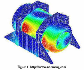
Heat Transfer analysis models the conductivity
or thermal fluid dynamics of the material or structure (Figure
1). This may consist of a steady-state or transient transfer.
Steady-state transfer refers to constant thermoproperties in
the material that yield linear heat diffusion.
Results of Finite Element Analysis
FEA has become a solution to the task of predicting
failure due to unknown stresses by showing problem areas in a
material and allowing designers to see all of the theoretical
stresses within. This method of product design and testing is
far superior to the manufacturing costs which would accrue if
each sample was actually built and tested.
Submitted by Peter Widas
Last updated: 4/8/97
Virginia Tech Material Science and Engineering

 Types of Engineering Analysis
 Fatigue analysis
helps designers to predict the life of a material or structure
by showing the effects of cyclic loading on the specimen. Such
analysis can show the areas where crack propagation is most likely
to occur. Failure due to fatigue may also show the damage tolerance
of the material (Figure 5).