Numerical Examples of Fracture
Finite Element Analysis
Finite element analysis is a tool used in engineering to determine
the physical effects a given set of boundary conditions will have
on a part. Boundary conditions can be forces, temperatures, hydrostatic
pressures, centrifugal pressures, torques, and displacements.
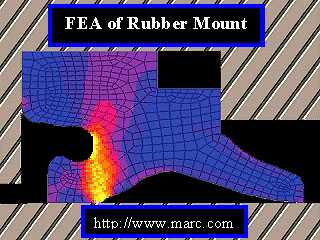 Finite element analysis can be as basic as a simple
FORTRAN code or as complex as some
of today's high end Finite Element Analysis
Software Packages (MARC). The basic theory
of finite element analysis is the
same regardless of the type of analysis being done. The geometry
being modeled will always be divided up into smaller divisions
known as elements and the elements are connected together to form
the finite element mesh. Each element contains nodes which are
points were the elements are mathematically connected to one another.
The idea of dividing a domain up into subdomains is the basic
principle of how FEA works.
The basic steps which are involved in creating a finite element
model are now going to be outlined as we create a plain strain
model of an infinite plate, with an elliptical hole in the middle,
loaded in the simple tension. This model represents one of the
basic ideas of fracture mechanics, stress intensity. This problem
also has an analytical solution with which we can compare our
FEA results to determine the validity of our model.
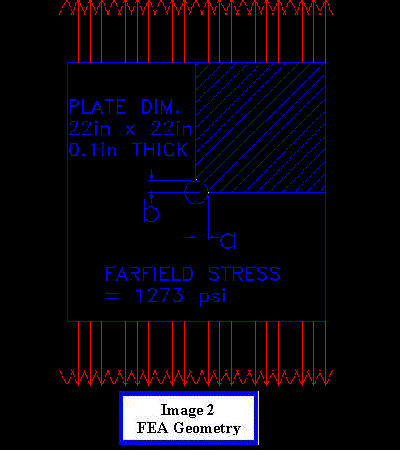 The first step in creating a finite element model is to input
the geometry of the part you want to model. Often the geometry
being modeled will have some type of symmetry, which can be taken
advantage of to save time both generating the model and solving
the model. As you can see only ¼ of the geometry (the crosshatched
section of Image 2) will need to be modeled to
look at the stress intensity at the transverse side of the
elliptical hole. After the geometry has been created the next
step is to turn the surface of the plate into a mesh. For this
model we will use a four-sided element with a node at each corner.
A technique commonly used in FEA is mesh biasing. Mesh biasing
is using smaller elements in areas where the stress gradient is
the large or in areas where an extremely accurate prediction of
stress is necessary. In this model we biased the mesh towards
elliptical hole to produce an accurate value of the stress intensity.
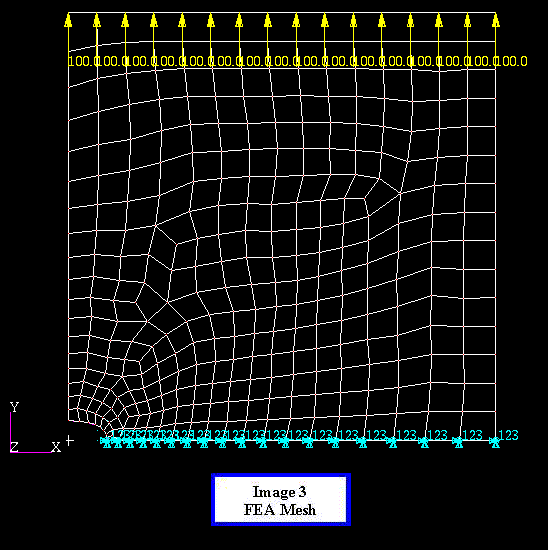 Since we are only modeling part of the plate it is important
that add the correct boundary conditions to simulate the same
effects that would occur if the entire plate were being modeled.
The only things we will need to add are displacement restraints
on the bottom edge of the model perpendicular to the direction
of the loading. We want to induce a Farfield Stress of 1273 psi
in the plate so we will put a 100-LB tensile force on each node
across the top of the plate. This completes the boundary conditions
for the model.
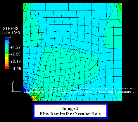 Now we must define the material properties for the elements,
in this model we will use the physical properties of steel, modulus
of elasticity 30 *10^6 psi and poison ratio of 0.30. This completes
the finite element model, now we will submit the model to a solver,
ABAQUS was used for this model, which will return the geometry
with the stress levels indicated by different colors.
The results of an FEA from most software packages look fairly
similar to the output of the above model. The areas of highest
stress are indicated by red, descending to the lowest stress levels
in blue. The next task is to determine whether or not the results
our model produced are accurate. In this case we can obtain an
exact solution to our model using the analytical solution to the
stress concentration produced by an elliptical hole in an infinite
plate under simple tension, which given by the relationship:

where "a" and "b" are both parameters
of the ellipse (shown in second image).
In this model the ellipse was actually a circle so the stress
concentration is just three times the Farfield Stress, which gives
a stress concentration of 3819 psi. The FEA returned the stress
concentration at the hole to be 4050 psi, which is 6% higher than
the exact solution. The 6% error would be reasonable for most
engineering design
applications because an exact solution is not critical
because a factor of safety will be added in the part design.
 Next we will examine the same plate with two smaller "b"
values for the ellipse. Decreasing the "b" of the ellipse
is analogous to decreasing the radius of a crack tip in crack.
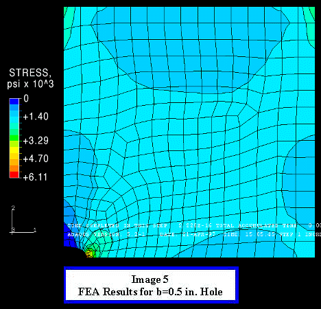
In the next model "b" decreases to 0.5 in. Again
we have the luxury of being able to calculate an exact solution
for the stress concentration, which is five times the Farfield
Stress, 6365 psi. The FEA result was 6110 psi, which is 4% lower
than the exact solution. Again this small error negligible,
however inspecting the stress as you approach the crack tip from
the right reveals a very large stress gradient across a very small
number of elements. This model still produces a valid solution
but we will see that when "b" is reduced to 0.25 in.
the mesh size around the crack tip is too large to produce a valid
solution. When "b" is reduced to 0.25 in. the analytical
solution for the stress concentration becomes nine times
  the Farfield
stress, 11457 psi. However the FEA only shows a stress concentration
of 7010 psi. This large error, 38%, is due to the fact the stress
gradient is so large across the elements next to the crack tip
that they no longer yield valid solutions. The corrective action
for this problem would be to decrease the element size around
the crack tip, resulting in more elements around the crack tip.
With increased exposure to FEA one would learn to question results
that come from a mesh which has such a large stress gradient over
a small number of elements.
Thus we can see that an FEA can produces highly accurate results
of stress concentration when the mesh is sized reasonably well
compared to the stress gradient and the same rule holds true for
any type of FEA. However in real engineering applications there
will be no exact solution to the models. Engineers must depend
on their knowledge and intuition to determine whether the results
of an FEA are valid.
Further Reading:
- Theory of Elasticity, Timoshenko and Goodier.
- Engineering Fracture Mechanic: Numerical Methods and Applications,
D.R.J. Owens and A.J. Fawkes.
- An Introduction to the Finite Element Method, J.N.
Reddy.
Special Thanks to:
- Prof. Ron Kriz, Dept. of Materials Science and Engineering,
Dept. of Engineering Science and Mechanics.
- Mike Pastor, Graduate Student Engineering Science and
Mechanics.
- Axinte Ionite, Graduate Student Engineering Science
and Mechanics.
- Duane Taylor, System administrator Dept. of Engineering
Science and Mechanics.
- Dept. of Materials Science and Engineering.
- Dept. of Materials Science and Mechanics.
This page was written by Jeff Schultz.
Revised 4-24-97
 Finite element analysis can be as basic as a simple
FORTRAN code or as complex as some
of today's high end Finite Element Analysis
Software Packages (MARC). The basic theory
of finite element analysis is the
same regardless of the type of analysis being done. The geometry
being modeled will always be divided up into smaller divisions
known as elements and the elements are connected together to form
the finite element mesh. Each element contains nodes which are
points were the elements are mathematically connected to one another.
The idea of dividing a domain up into subdomains is the basic
principle of how FEA works.
The basic steps which are involved in creating a finite element
model are now going to be outlined as we create a plain strain
model of an infinite plate, with an elliptical hole in the middle,
loaded in the simple tension. This model represents one of the
basic ideas of fracture mechanics, stress intensity. This problem
also has an analytical solution with which we can compare our
FEA results to determine the validity of our model.
 The first step in creating a finite element model is to input
the geometry of the part you want to model. Often the geometry
being modeled will have some type of symmetry, which can be taken
advantage of to save time both generating the model and solving
the model. As you can see only ¼ of the geometry (the crosshatched
section of Image 2) will need to be modeled to
look at the stress intensity at the transverse side of the
elliptical hole. After the geometry has been created the next
step is to turn the surface of the plate into a mesh. For this
model we will use a four-sided element with a node at each corner.
A technique commonly used in FEA is mesh biasing. Mesh biasing
is using smaller elements in areas where the stress gradient is
the large or in areas where an extremely accurate prediction of
stress is necessary. In this model we biased the mesh towards
elliptical hole to produce an accurate value of the stress intensity.
 Since we are only modeling part of the plate it is important
that add the correct boundary conditions to simulate the same
effects that would occur if the entire plate were being modeled.
The only things we will need to add are displacement restraints
on the bottom edge of the model perpendicular to the direction
of the loading. We want to induce a Farfield Stress of 1273 psi
in the plate so we will put a 100-LB tensile force on each node
across the top of the plate. This completes the boundary conditions
for the model.
 Now we must define the material properties for the elements,
in this model we will use the physical properties of steel, modulus
of elasticity 30 *10^6 psi and poison ratio of 0.30. This completes
the finite element model, now we will submit the model to a solver,
ABAQUS was used for this model, which will return the geometry
with the stress levels indicated by different colors.

 Next we will examine the same plate with two smaller "b"
values for the ellipse. Decreasing the "b" of the ellipse
is analogous to decreasing the radius of a crack tip in crack.
In the next model "b" decreases to 0.5 in. Again
we have the luxury of being able to calculate an exact solution
for the stress concentration, which is five times the Farfield
Stress, 6365 psi. The FEA result was 6110 psi, which is 4% lower
than the exact solution. Again this small error negligible,
however inspecting the stress as you approach the crack tip from
the right reveals a very large stress gradient across a very small
number of elements. This model still produces a valid solution
but we will see that when "b" is reduced to 0.25 in.
the mesh size around the crack tip is too large to produce a valid
solution. When "b" is reduced to 0.25 in. the analytical
solution for the stress concentration becomes nine times
  the Farfield
stress, 11457 psi. However the FEA only shows a stress concentration
of 7010 psi. This large error, 38%, is due to the fact the stress
gradient is so large across the elements next to the crack tip
that they no longer yield valid solutions. The corrective action
for this problem would be to decrease the element size around
the crack tip, resulting in more elements around the crack tip.
With increased exposure to FEA one would learn to question results
that come from a mesh which has such a large stress gradient over
a small number of elements.
Thus we can see that an FEA can produces highly accurate results
of stress concentration when the mesh is sized reasonably well
compared to the stress gradient and the same rule holds true for
any type of FEA. However in real engineering applications there
will be no exact solution to the models. Engineers must depend
on their knowledge and intuition to determine whether the results
of an FEA are valid.