SHADE_SURF Procedure
Creates a
shaded surface representation of a regular or nearly regular gridded surface, with shading from either a light source model or from a specified array of intensities.
Usage
Input Parameters
z  A two-dimensional array containing the values that make up the surface. If x and y are supplied, the surface is plotted as a function of the X,Y locations specified by their contents. Otherwise, the surface is generated as a function of the array index of each element of z.
x  A vector or two-dimensional array specifying the x-coordinates for the contour surface. If x is a vector, each element of x specifies the x-coordinate for a column of z.
For example, x(0) specifies the x-coordinate for z(0, *). If x is a two-dimensional array, each element of x specifies the x-coordinate of the corresponding point in z (xij specifies the x-coordinate for zij).
y  A vector or two-dimensional array specifying the y-coordinates for the contour surface. If a vector, each element of y specifies the y-coordinate for a row of z.
For example, y(0) specifies the y-coordinate for z(*, 0). If y is a two-dimensional array, each element of y specifies the y-coordinate of the corresponding point in z (yij specifies the y-coordinate for zij).
Keywords
Image  The name of a variable into which the image containing the shaded surface is stored. If this keyword is omitted, the image is displayed but not saved.
Max_Img_Size  For devices with scalable pixels (e.g., postscript), this keyword sets the largest allowed image size created internally to render the shaded surface. Larger values will result in a better quality image but at a cost of greater memory use and larger file size. The mimimum value is 100 (100x100), which will generally result in a poor-quality image. (Default: 400)
Shades  An array expression, of the same dimensions as z, containing the color index at each point. The shading of each pixel is interpolated from the surrounding Shades values. For most displays, this parameter should be scaled into the range of bytes. If this keyword is omitted, light source shading is used.
Other keywords are listed below. For a description of each keyword, see Chapter 3, Graphics and Plotting Keywords.
Discussion
CAUTION: If the T3D keyword is set, the 3D to 2D transformation matrix contained in !P.T must project the z-axis to a line parallel to the device y-axis, or errors will occur.
If the X,Y grid is not regular or nearly regular, errors in hidden line removal will likely occur. In this case, you should use the SHADE_SURF_IRR procedure.
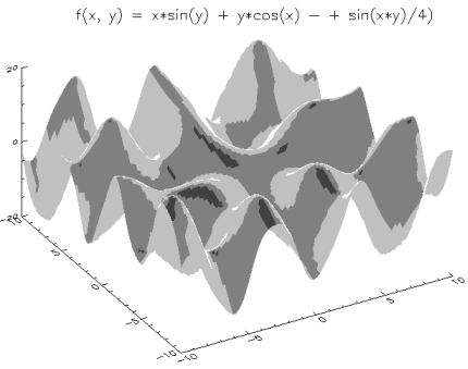
Example 1
x = FINDGEN(101)/5 -10
y = x
z = FLTARR(101, 101)
FOR i = 0, 100 DO BEGIN $
 z (i, *) = x(i)*SIN(y) + y*COS(x(i)) $
- SIN(0.25*x(i)*y)
SHADE_SURF, z, x, y, Ax = 50, XCharsize = 2, $
    YCharsize = 2,ZCharsize = 2
XYOUTS, 118, 463, $
    "f(x, y) = x*sin(y) + y*cos(x) - + sin(x*y)/4)", $
    Charsize = 2, /Device
Figure 2-105 Shaded surface with title.
Figure 2-106 Shaded surface with title.
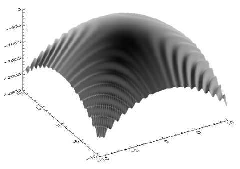
Example 2
x = FINDGEN(101)/5 - 10
y = x
x = x # REPLICATE(1., 101)
y = REPLICATE(1., 101) # y
z = x * y * cos(0.575 * x * y) - 10 * (x^2 + y^2)
OPENW, 1, 'shsurf.dat'
data = FLTARR(3, 101, 101)
data(0, *, *) = x
data(1, *, *) = y
data(2, *, *) = z
PRINTF, 1, Format = '(3f16.7)', data
CLOSE, 1
data = FLTARR(3, 101, 101)
OPENR, 1, 'shsurf.dat'
READF, 1, data
CLOSE, 1
x = REFORM(data(0, *, *))
y = REFORM(data(1, *, *))
z = REFORM(data(2, *, *))
SHADE_SURF, z, x, y, Ax = 50, Charsize = 2
Figure 2-107 Shaded surface defined in the example.
Figure 2-108 Shaded surface defined in the example.
Example 3
SHADE_SURF, DIST(100), Ax=60
See Also


doc@boulder.vni.com
Copyright © 1999, Visual Numerics, Inc. All rights
reserved.
 A two-dimensional array containing the values that make up the surface. If x and y are supplied, the surface is plotted as a function of the X,Y locations specified by their contents. Otherwise, the surface is generated as a function of the array index of each element of z.
 A vector or two-dimensional array specifying the x-coordinates for the contour surface. If x is a vector, each element of x specifies the x-coordinate for a column of z.
 A vector or two-dimensional array specifying the y-coordinates for the contour surface. If a vector, each element of y specifies the y-coordinate for a row of z.


