|
Building ANSYS Model
|
NODE LOCATIONS:
First, it was necessary to recreate the cylinder in ANSYS. This begins with locating all of the nodes in the I-DEAS model and determining how the coordinate system information and locations are output from IDEAS
This data is simply output in the format of :
 |
|
Ideas Node Location Formatting
|
The cylinder was built along the Y axis, therefore the X and Z coordinates were grouped in the output file. This information is in the IDEAS output file header and can be deciphered from the documentation provided by IDEAS
Here is the output file from IDEAS
| Node_coords_only.txt |
Knowing that the file was output using a specific coordinate system, the next step is to rearrange the nodes for input into ANSYS. For this step, a Matlab code (FE_Node_coords_XYZ) was written to just rearrange the coordinates for entry into ANSYS. This nodal data was then reformatted for entry into ANSYS following the format in table 1, below:
 |
|
ANSYS node format
|
| Corner_Node_loc_for_Ansys.txt |
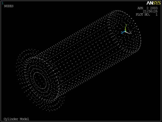
This nodal information was inserted into the ANSYS Batch file to create the same nodes in an ANSYS model as were used to create the IDEAS model. The nodes created by the ANSYS Batch file appeared as follows:
 |
Cylinder Nodes |