|
Building ANSYS Model
|
Face-plate Connection & Spring Elements:
In the IDEAS model, a set of stiff 1-D bar (or Truss) Elements
were used to simulate the rigid connection between the face-plate and the cylinder.
And another set of flexible 1-D bar (or Spring) elements were used to constrain
the model from rigid body motion. Analogous Link Elements with varying stiffnesses
were used in a similar fashion in the ANSYS model. Like the Shell Elements,
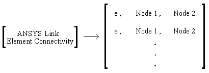
in the previous section, the connectivity for these elements has to be arranged
specifically for the ANSYS.
 |
|
ANSYS Link Element Information
|
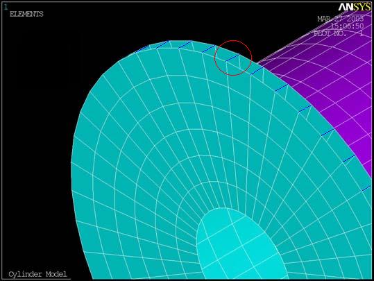
The element information for the rigid connection of the face plate and flange and the spring elements were inserted into the ANSYS batch file to create these link elements in the ANSYS model. The link elements connecting the face plate and flange are shown immediately below.
 |
Rigid Bars |
The spring elements can be seen below: