Crane Ship Simulator – Status Report
Abstract
A crane ship simulator in a Computer Automated Virtual Environment (CAVETM) is being developed at Virginia Tech. A motion platform will be used to provide motion queuing to the user of this simulator. The user will be immersed in a virtual environment, with a four-wall CAVETM (which has three vertical walls and a floor), motion base with operator seat, control console with joystick crane controls, and four-channel sound. (http://thor.sv.vt.edu/crane/)
General virtual prototyping system
The crane ship simulator system is being constructed with an existing CAVETM system. Since this CAVETM is being used by many other unrelated projects, the development of the crane ship simulator is driving the development of a general virtual prototyping system due to necessity, in order for this crane ship simulator to co-exist with other unrelated projects in this CAVETM and motion based system. The crane operator seat and console assembly is a single piece and has a mass of less than one hundred kilograms, so that it can easily be removed or replaced with a different unit in a matter of minutes. All other hardware components of the crane ship simulator are not specifically made for just the crane ship simulator and can be used with other projects. The crane operator seat and console assembly may also be used with other projects. This CAVETM and motion based system has the unique ability to be reconfigured in minutes. The modular structure of the hardware and software of this system enable it to be a general virtual prototyping system as any CAVE-like system, but with the additional feature of user motion queuing. It is believed that the motion will make the CAVETM an even more immersive environment, which will make it a more effective tool.
Virginia Tech CAVETM
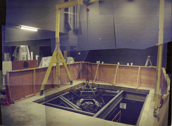
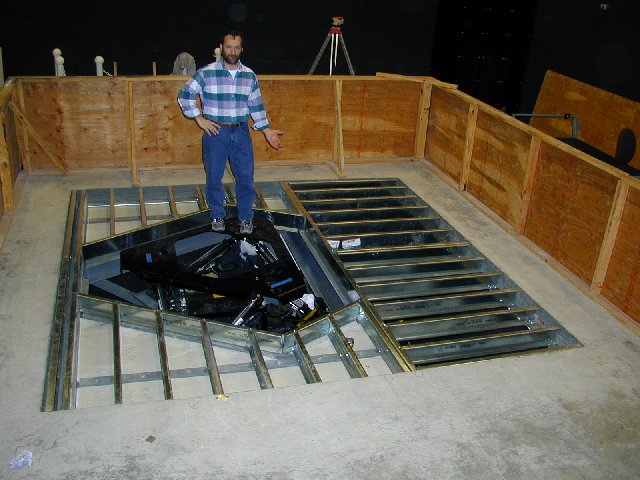
Significant progress has been made on constructing the CAVETM floor support structure for the motion platform and CAVE TM.

Figure 1 January 16, 2001, Room 3090 Torgersen Hall, Virginia Tech: a rough composite image of the MOOG motion base being lowered into the floor.

Figure 2 February 6, 2001, Room 3090 Torgersen Hall, Virginia Tech: the floor with joists at the time of the writing of this report.
We estimate that the construction of the building floor will be completed by February 9, 2001. The construction of the CAVETM we project to be completed around the first week of March 2001.
Software Design
The simulator system structure is a cluster of cooperating programs. These programs are coupled to each other by fixed data structures that retain the current state information of the system in interprocess shared memory from which the programs can read and write. This design facilitates a modular structure for the system. All the programs in the simulator run asynchronously with respect to all other programs. Some programs consist of more than one process or thread. Some programs are simulating physical dynamical models whose cyclic solver is synchronized to real-time.
The DIVERSE Toolkit (http://www.diverse.vt.edu/DTK/)
The DIVERSE Toolkit (DTK) is the "glue" that ties together the programs in the simulator. Briefly, DTK consists of the server program, a C++ client application programming interface (API) and small utility programs. The DTK server manages the interprocess shared memory, provides an interface for other programs to serial hardware devices via shared memory, and a seamless interface to IP networked shared memory. All programs in the simulator use the DTK C++ client API. The DTK server is central to the system in that it is the only program required to be running at all times for the simulator to be running. All of the other programs (modules) can be developed and run independently of most other modules. Modules can be emulated and started and stopped without corrupting other running modules. When the system is running in a steady state the primary interprocess communication (IPC) mechanism used is DTK interprocess shared memory.
The largest difference between this programming paradigm and one using message passing interface (MPI) is that the programs distributed in this system typically run asynchronously. The network IPC methods in DTK are usually unreliable (i.e., UDP/IP). However, reliable TCP/IP is used for changing the system configuration, like adding an observer to the system or communicating discrete events, such as turning on a light. The UDP/IP methods are used for transferring most of the network information, such as when a model of a hydraulic cylinder is continuously expanding and contracting due to an operator's input. The changes in the cylinder's length are being fed to the network continuously at a regular rate. If a cylinder length network IP packet is lost, there will not be a need to send again that information because, in most cases, the next cylinder length packet will come before a replacement IP packet can arrive. This method is analogous to the way real systems interact. For example, if you blink your eyes, the light that your eyes did not receive is not sent again, but instead the latest light information is sent to your eyes when you reopen them.
Integration design of programs (modules) in the simulator system
The simulator programs contain DTK client objects that enable the making of DTK shared memory objects that in turn enable communication between the programs in the system. The code in the programs may be written in any combination of languages that may be linked with C++ objects, which includes FORTRAN, C, and C++.
Most of the programs in the system, after being initialized, run in a cyclic steady state simulation loop. For this case the programs code may be split into two logical functions (subroutines or methods), "initialization" and "cyclic advance." In the case of a C++ implementation a class constructor may be used for initialization. A possible third function can be "closure" for the removal of shared computational resources that may have been allocated when the program runs, so that the program may call this function before exiting. We refer to the code of these functions as "task functions." The writing of the task functions does not require the use of the DTK API. For programs that must run in real-time, the real-time synchronizing code is not included in these task functions, but is introduced outside of these task functions, so that the code of these task functions may be used on other platforms, in other applications and testing the code is easier. The task functions provide enough output variables so that any needed changing system state information, like for example position, angular acceleration, and time can be gotten from the output variables. The task functions provide enough input variables so that all changing inputs are passed to the task functions. The code of these task functions may preserve the dynamical state of its task or the dynamical state of its task may be passed to the task functions as a combination of input/output variables. The later case may be more resource (CPU and memory usage) efficient in some cases. When possible the cyclic advance task function should allow the user to specify the time to advance to.
List of Simulator System
Modules (running programs)
All of the simulator modules will continually evolve. The modules marked as done are currently in a usable state.
- DTK: server system service provider (done)
- Render: drawing visual (done)
- Wave: compute wave height and ship's x and y position relative to the ocean grid (done)
- LAMP: (http://www.ship.saic.com/) ship hull dynamics model (done)
- Fun Filter: visual and motion base relative motion filter
- Crane Model: crane dynamics model
- Crane Controller filter operator input to crane model
- Motion Base Controller is a controller for engaging and shutting down the MOOG motion base (done)
- Sound simulation activated sound